40 ASUS A7V User’s Manual
Connectors
3. H/W SETUP
3. HARDWARE SETUP
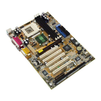
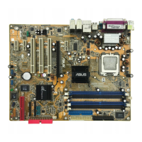
15) Internal Audio Connectors (4-pin CD_IN, AUX, VIDEO, MODEM)
These connectors allow you to receive stereo audio input from such sound sources
as a CD-ROM, TV tuner, or MPEG card. The MODEM connector allows the
onboard audio to interface with a voice modem card with a similar connector.
AUX (White)
Right Audio Channel
Left Audio Channel
Ground
A7V Internal Audio Connectors
MODEM
Modem-Out (from Modem)
Ground
Modem-In (to Modem)
CD (Black) VIDEO (Green)
Right Audio Channel
Left Audio Channel
Ground
0 1
0 1
0 1
A7V
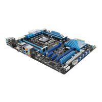
16) Internal Microphone Header (3-pin MIC2)
This connector allows you to connect a chasssis mounted microphone to the mother-
board instead of having to attach an external microphone onto the ATX connectors.
MIC Power
MIC Input
GND
A7V Microphone Header
0 1
0 1
0 1
A7V
MIC2
1
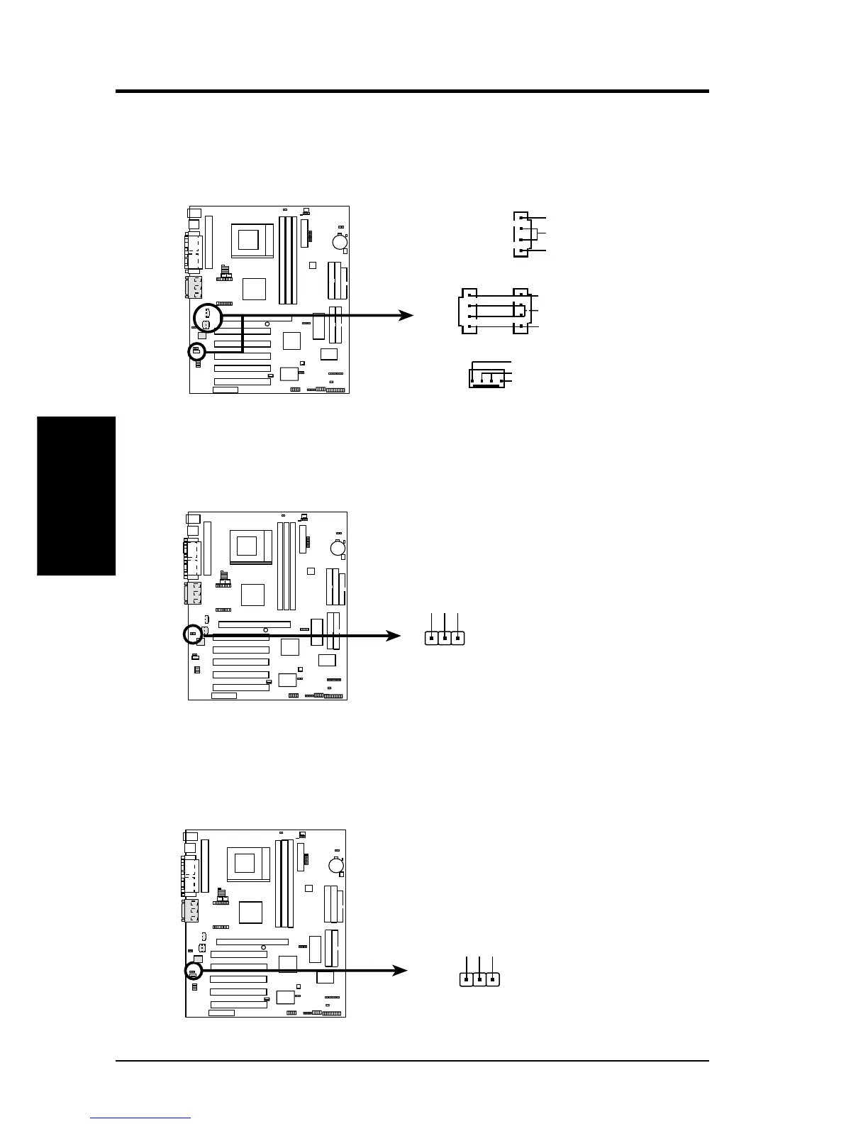
17) Headphone True-Level Out Header (3-pin HPHONE)
This connector allows you to connect a chassis mounted headphone to the mother-
board instead of having to attach an external headphone onto the ATX connectors.
A7V True-Level Line Out Header
1
HPHONE
HP OUT LT
GND
HP OUT RT
0 1
0 1
0 1
A7V