Do you have a question about the Asus RS700A-E12 Series and is the answer not in the manual?
Precautions for safe electrical handling during installation and operation.
Guidelines for safe mechanical operations and general usage of the server.
Specifies requirements for the server's installation environment regarding access control.
Covers warnings for Lithium-Ion batteries, system weight, and optical drive laser safety.
Defines the intended users of the guide, such as system integrators.
Summarizes the content of each chapter within the user guide.
Explains text formatting, key notation, and warning symbols used in the manual.
Lists additional resources for product and software updates.
Lists all components included in the server package, both standard and optional.
Explains the location and format of the product's serial number for support purposes.
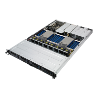
Details hardware specifications including CPU, memory, slots, and storage.
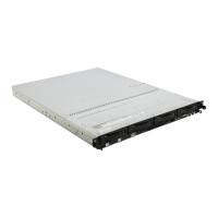
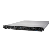
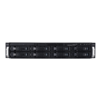
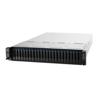
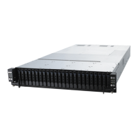
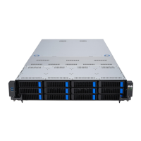
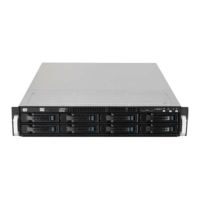
Describes the components and indicators located on the server's front panel.
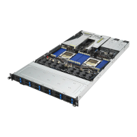
Details the connectors, slots, and controls found on the server's rear panel.
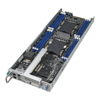
Identifies and illustrates the main internal components of the server system.
Explains the status and meaning of LEDs on the server's front panel.
Describes the LEDs indicating the status of SATA/SAS storage devices.
Details the activity and speed LEDs for the server's LAN ports.
Explains the Power and Location LEDs found on the server's rear panel.
Provides a detailed list of POST codes, their actions, phases, types, and descriptions.
Instructions for removing the rear and backplane covers of the server chassis.
Covers the removal and installation procedures for the server's air ducts.
Details installing CPUs into sockets and mounting CPU heatsinks.
Information on DIMM sockets, configurations, installation, and removal.
Instructions for removing and installing the optional front bezel for security.
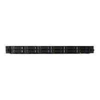
Describes the server's 2.5-inch hot-swap storage bays and drive support.
Instructions for installing an expansion card into the main PCIe riser bracket.
Procedure for installing an OCP 3.0 card into the designated slot.
Instructions for installing an expansion card into the butterfly riser bracket.
Details installing 1GbE or 10GbE LAN cards into the butterfly riser.
Procedure for installing an HBA/RAID card into the butterfly riser bracket.
Steps to disconnect and remove an HBA/RAID card from the butterfly riser.
Instructions for installing the cache vault power module onto the riser bracket.
Guide for installing M.2 cards into the motherboard's onboard slots.
Explains how to configure installed expansion cards, including BIOS settings and IRQ assignments.
Details pre-connected system cables and refers to connector information.
Illustrates cabling connections for storage devices to the backplane and motherboard.
Details the cabling and configuration for 12 SATA storage devices.
Outlines the cabling and configuration for 4 NVMe storage devices.
Details the cabling and configuration for 8 NVMe storage devices.
Outlines the cabling and configuration for 12 NVMe storage devices.
Details the cabling for 8 SAS and 4 SATA storage devices.
Covers the installation and uninstallation procedures for system fans.
Guide on installing an optional external rear fan, typically with GPU cards.
Procedure for replacing a failed redundant power supply module.
Details the tool-less friction rail kit and its installation into the rack.
Provides the physical dimensions of the tool-less rail kit components.
Information on the ball bearing rail kit components and its attachment to rack rails.
Instructions for installing the optional cable management arm onto the rack rails.