PONG 4 P D&B Manual
11/18/2019
84
1
1
2
2
3
3
4
4
5
5
6
6
7
7
8
8
D D
C C
B B
A A
Name:
Date:
Version:
=CurrentDate
1
2
3
4
5
6
7
8
9
A
B
C
D
E
F
G
H
I
brown
red
orange
yellow
green
blue
violet
grey
white
black
pink
light green
sky blue
shield layer
J
K
L
M
N
O
P
Q
AWG30 UL1007
AWG28 UL1007
AWG26 UL1007
AWG24 UL1007
AWG22 UL1007
AWG20 UL1007
AWG18 UL1007
AWG16 UL1007
Note: Wire color and wire size is shown in code.
Wire color code
Wire size code
Tolerance
unit mm
scale
:
0~1000
1001~2000
2001~3000
3001~4000
4001~5000
±10
±20
±30
±40
±50
j
k
L
m
n
o
p
q
r
AWG30 UL1015
AWG28 UL1015
AWG26 UL1015
AWG24 UL1015
AWG22 UL1015
AWG20 UL1015
AWG18 UL1015
AWG16 UL1015
AWG14 UL1015
Wire size code
Example 2 0 m
Color of the wire: 20 means red
Size of the wire: m means AWG24 UL1015
Universal Spa ce
Amusement machine
UNIS
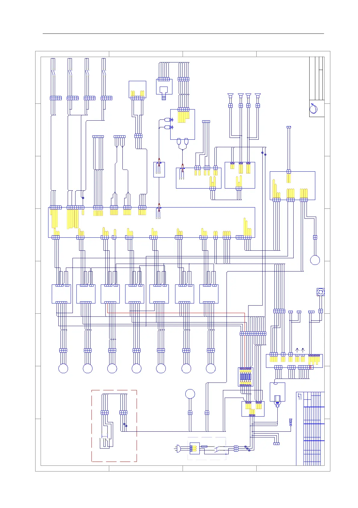
PONG 4P D&B Wiring Diagram 1
PPSR-PX-00-01C
Audio port
1
2
3
4
MOT-J2
Pong Main V2.1
1
2
3
4
XH
10P
Pulse
45Q
GND
60P
Direction
Power supply
24V/350W
GND
24V
Red player Speaker
Noise filter
FUSE
T6A
Power switch
SW DPST
Earth
PLUG
Filter
N
L
E
40P
A0P
Red player motor
50
1
2
3
4
P
A0
1
2
3
4
J03
C
M542C
1
2
3
4
ACC
GND
DIR-
PUL+
1
2
3
4
5
6
B-
B+
A-
A+
PUL-
60
DIR+
20
Red driver
M
1
2
3
4
MOT-J1
1
2
3
4
XH
Pulse
GND
Direction
50
1
2
3
4
P
A0
1
2
3
4
J04
C
M542C
1
2
3
4
ACC
GND
DIR-
PUL+
1
2
3
4
5
6
B-
B+
A-
A+
PUL-
60
DIR+
20
Yellow driver
M
1
2
3
4
MOT-Y
1
2
3
4
XH
Pulse
GND
Direction
50
1
2
3
4
P
A0
1
2
3
4
J05
C
M542C
1
2
3
4
ACC
GND
DIR-
PUL+
1
2
3
4
5
6
B-
B+
A-
A+
PUL-
60
DIR+
20
Y driver
M
50
1
2
3
4
P
A0
1
2
3
4
J06
C
M542C
1
2
3
4
ACC
GND
DIR-
PUL+
1
2
3
4
5
6
B-
B+
A-
A+
PUL-
60
DIR+
20
Yellow player X driver
M
50
1
2
3
4
P
A0
1
2
3
4
J07
C
M542C
1
2
3
4
ACC
GND
DIR-
PUL+
1
2
3
4
5
6
B-
B+
A-
A+
PUL-
60
DIR+
20
Red player X driver
M
30P
A0P
60
50P
A0P
70
10
60
20
70P
A0P
50
A0
60
20
80P
A0P
50
A0
60
20
80
A0P
1
2
3
4
12V-IN
1
2
3
4
5557/4P
GND
12V
GND-
24V+
GND
24V
28
A0
A0P×2
A0P×2
10
A0
A0
10P
45Q
60P
Yellow player motor
Y motor
Yellow player X motor
Red player X motor
Power supply
20P
A0P
40P
A0P
50
A0
60
20
50
A0
60
20
4-cord cable
70
10
60
20
PPSR-PX-02
PPSR-PX-03
PPSR-PX-05
PPSR-PX-06
PPSR-PX-07
1
2
3
4
5
6
7
8
9
10
11
12
13
14
C
1
2
3
4
5
6
7
8
9
10
11
12
13
14
J10
P
A0P
A0P
A0P
A0P
A0P
A0P
A0P
A0P
A0P
A0P
PPSR-PX-17
PPSR-PX-18
40P
A0P
GND
24V
80P×2
80P×2
1
2
MF+
MF-
1
2
MF+
MF-
1
2
MF+
MF-
1
2
MF+
MF-
1
2
MF+
MF-
A0
A0
A0
A0
1
2
EN
1
2
XH
Enable
90
90
90
90
90
A0
A0
A0
A0
A0
A0
Audio port
Audio isolator
A0
50
15
16
15
16
1
2
3
4
P2
1
2
3
4
P
A0Q
A0Q
40Q
40Q
40
40
11
10
11
10
P1
A0
77
1717
A0
2424
1
2
3
4
P4
1
2
3
4
JHD5084HP/4P
40O
A0O
A0O
20O
1
2
3
4
J1
1
2
4
3
VH
GND
1
2
J3
GND
1
2
VH
12V/4=F3
12V/6=F2
Fuseboard01(V1.0)
GND
GND
12V
12V
GND
5V
GND
12V/2=F4
J2
FUSE F5A/250V
F1
F2
F3
F4
F5
F6
F1
F2
F3
F4
F5
F6
FUSE BOARD 02(V1.0)
1
2
3
4
5
6
C
1
2
3
4
5
6
J11
P
A0P
A0P
40P
40P
A0P
A0P
40P
40P
20P
A0P
20P
A0P
MOTOR P1
MOTOR P2
MOTOR Y
AMP
MOTOR X
90
50
AC L
AC N
Earth
A0P
50P
90P
1
2
3
4
MOT-X2
1
2
3
4
XH
Pulse
GND
Direction
1
2
3
4
MOT-X1
1
2
3
4
XH
Pulse
GND
Direction
20P
A0P
1
2
5V-IN
1
2
VH
GND
5V
GND
12V
40P
A0P
1
2
3
J02
HM
10P
45Q
60P
Wiring cap
96
95
RW
1
2
3
4
5
6
CON1
L soundtrack1
L soundtrack2
GND
R soundtrack1
R soundtrack2
GND
1
2
3
4
5
6
XH
A0M
E
30M
50M
40M
20M
VR
50K POT
1
2
3
4
5
6
XH
1
2
3
4
5
6
CN1
VRPCB
A0M
E
30M
50M
40M
20M
AUDIO 1
AUDIO2
10P
45Q
60P
1
2
3
HM
1
2
3
J01
HF
1
2
P
1
2
J26
C
90
50
+
-
TO PPSR-PX-00-03
80P×2
A0P×2
M4-MB.PCB
30P
50P
70P
80P
90P
30P
50P
70P
80P
90P
10
20
A0
30
40
A0
50
60
A0
70
80
A0
91
92
A0
90
1
2
3
4
MOT-J4
1
2
3
4
XH
Pulse
GND
Direction
Blue player motor
50
1
2
3
4
P
A0
1
2
3
4
J08
C
M542C
1
2
3
4
ACC
GND
DIR-
PUL+
1
2
3
4
5
6
B-
B+
A-
A+
PUL-
60
DIR+
20
Blue player driver
M
93
94
A0
1
2
3
4
MOT-J3
1
2
3
4
XH
Pulse
GND
Direction
50
1
2
3
4
P
A0
1
2
3
4
J09
C
M542C
1
2
3
4
ACC
GND
DIR-
PUL+
1
2
3
4
5
6
B-
B+
A-
A+
PUL-
60
DIR+
20
Green player driver
M
95
96
A0
10P
A0P
60P
A0P
Green player motor
1
2
MF+
MF-
1
2
MF+
MF-
A0
A0
90
90
A0
A0
A0
1
2
3
4
5
6
BUTTON-J1
1
2
3
4
5
6
XH/6P
Red player L shoot button
GND
Red player Start button
1
2
3
4
5
6
J14
C
1
2
3
4
5
6
P
Red player R shoot button
A0A0
L shoot button
10
R shoot button
20
A0
10 10
20 20
1
2
3
4
5
6
7
8
9
INPUT
1
2
3
4
5
6
7
8
9
XH/9P
Yellow player Shoot button
Yellow player Start button
GND
Blue player Shoot button
Blue player Start button
Green player Shoot button
Green player Start button
1
2
3
4
5
6
J15
C
1
2
3
4
5
6
P
A0
91
92
A0
91
1
2
3
4
5
6
J16
C
1
2
3
4
5
6
P
A0
10
20
A0×2
10
1
2
3
4
5
6
J17
C
1
2
3
4
5
6
P
A0
91
92
91
10P
60P
10P
60P
MOTOR P3
MOTOR P4
30P
50P
70P
80P
90P
10P
60P
A0P
A0P
A0P
A0P
A0P
1
2
3
4
5
6
J25
5559/6P
1
2
3
4
5
6
5557/6P
A0M
E
30M
50M
40M
20M
A0M
E
30M
50M
40M
20M
Wiring cap
Yellow player Speaker
90
50
1
2
P
1
2
J27
C
90
50
+
-
Blue player Speaker
1
2
P
1
2
J28
C
90
50
+
-
Green player Speaker
1
2
P
1
2
J29
C
90
50
+
-
96
95
PPSR-PX-04A
PPSR-PX-16
PPSR-PX-09
PPSR-PX-10
PPSR-PX-15
PPSR-PX-08
1
2
3
4
C4501HM
1
2
3
4
J98
C4501HF
10P
60P
60P
10P
Platform motor control switch
SW-DPDT
10P
60P
10P
10P
80P
A0P
Platform lifting motor 1(Red Player)
M
60P
10P
80P
A0P
1
2
C4501HF
1
2
J99
C4501HM
60P
10P
80P
A0P
60P
10P
80P
A0P
1
2
J100
C4501HM
60P
10P
Wiring cap
2.0 Amplifier
90×2
50×2
96×2
95×2
SPKL+
1
2
3
4
XH
B
A0
20
10
1
2
3
4
J3
3.3V
GND
Marquee black light
Platform motor detection
1
2
3
4
J4
1
2
3
4
5557/4P
MOT+ IN
MOT- IN
MOT+ OUT
MOT- OUT
1
2
3
4
J1
24V1
2
3
4
VH
GND
1
2
J2
1
2
VH
24V
LED
M
1
2
C4501HF
1
2
J101
C4501HM
60P
10P
Platform lifting motor 2(Blue Player)
1
2
C4501HF
60P
10P
60P
10P
60P
10P
60P
10P
1
2
J103
C4501HM
A0P
20P30P
A0P
1
2
3
4
5
6
7
8
LCD
VCC
GND
Marquee black light
1
2
3
4
5
6
7
8
XH/8P
Platform motor detection
B
A0
20
10
R
W
AUDIO2
24V
GND
PPSR-PX-49
PPSR-PX-50
PPSR-PX-54
1
2
J4
GND
5V
TO PPSR-PX-00-04-B1
Driver
90P
A0P
PPSR-PX-51
PPSR-PX-52A
A0P+A0
40P+40
PPSR-PX-54
A0P
40P
1
2
3
J102C
C4501HM
TO PPSR-PX-00-02-A3
2.1 Amplifier
1
2
J2
1
2
XH
24V
GND
28
A0
50
1
2
3
4
J113
C4501HM
90
50
96
95
1
2
3
OUTL
L+
L-
1
2
3
XH
1
2
3
OUTR
R+
R-
1
2
3
XH
90
50
96
95
1
2
3
IN1
1
2
3
XH
GND
Audio input L
20
A0
90
Audio input R
1
2
3
IN
1
2
3
XH
GND
Audio input L
Audio input R
20
A0
90
1
2
3
4
P
1
2
3
4
J114
C
Wiring cap
A0P
20P
1
2
J5
GND
5V
TO PPSR-PX-00-02-A2
1
2
VH
20P
A0P
1
2
J115
5559/2P
A0
20
FAN
12V
20
A0
1
2
C
1
2
J85
P
Fan
A0
40
1
2
3
4
5
PRG
XH
1
2
3
4
5
GND
SCK
SDO
VCC
RST
A0
E
50
40
20
1
2
3
4
5
6
J124
XH/6P
A0
E
50
40
20
LIGHT-01 V1.0
WM-024GT
HW-713
AUDIO V1.0
to update program
SPKL-
SPKR+
SPKR-
to Marquee speaker
to Marquee black light
To Marquee 12V power
To Marquee
Output AC100-240V
60P
10P
80P
A0P
20P+20
A0P +A0
1
2
J125
5559/2P
TO PPSR-PX-00-02-A1
To Machine surrounding
MAIN BOARD12V
Marquee12V
MAIN BOARD 5V
Marquee 5V
FRD2-156
45Q
Green player control panel GND connector
PS-6301-09
PPSR-PX-47A
PPSR-PX-48
50
A0
60
20
50
A0
60
20
50
A0
60
20
50
A0
60
20
50
A0
20
50
A0
60
20
50
A0
60
20
50
A0
60
20
A0
L shoot button
R shoot button
10
20
A0
L shoot button
R shoot button
10
20
A0
L shoot button
R shoot button
10
20
1
2
3
4
UART5
1
2
3
4
XH/4P
5V
GND
TXD
RXD
1
2
3
4
5
6
J105
C4501HM
E
90M
20M
E
90M
20M
E
90M
20M
1
2
3
4
UART6
1
2
3
4
XH/4P
5V
GND
TXD
RXD
1
2
3
4
UART4
1
2
3
4
XH/4P
5V
GND
TXD
RXD
E
90M
20M
To mainboard program update
PPSR-PX-57
TO PPSR-PX-00-04-C1
light 5V power
40
A0
E
20
1
2
3
4
J106
C2521HF-4P
1
2
3
4
HM
40
A0
E
20
PPSR-PX-56A
1
2
3
4
5
6
P1
GND
1
2
3
4
5
6
XH/7P
7
TXD
RXD7
40
A0
E
20
40
A0
E
20
VCC
CD9205
1
2
J6
GND
5V
TO PPSR-PX-00-02-D1
10. WIRING DIAGRAM
 Loading...