CHAPTER 7
Offset
00-01
02-03
04-05
06-07
14-15
16-17
18-21
22-23
28-29
30-31
32-35
36-37
Name
B
_
WD
B
_
HT
PLANE
_
CT
FG
_
COL
08-09 BG
_
COL
10-13 OP__TAB
S
_
XMIN
S
_
YMIN
S
_
FORM
S
_
NXWD
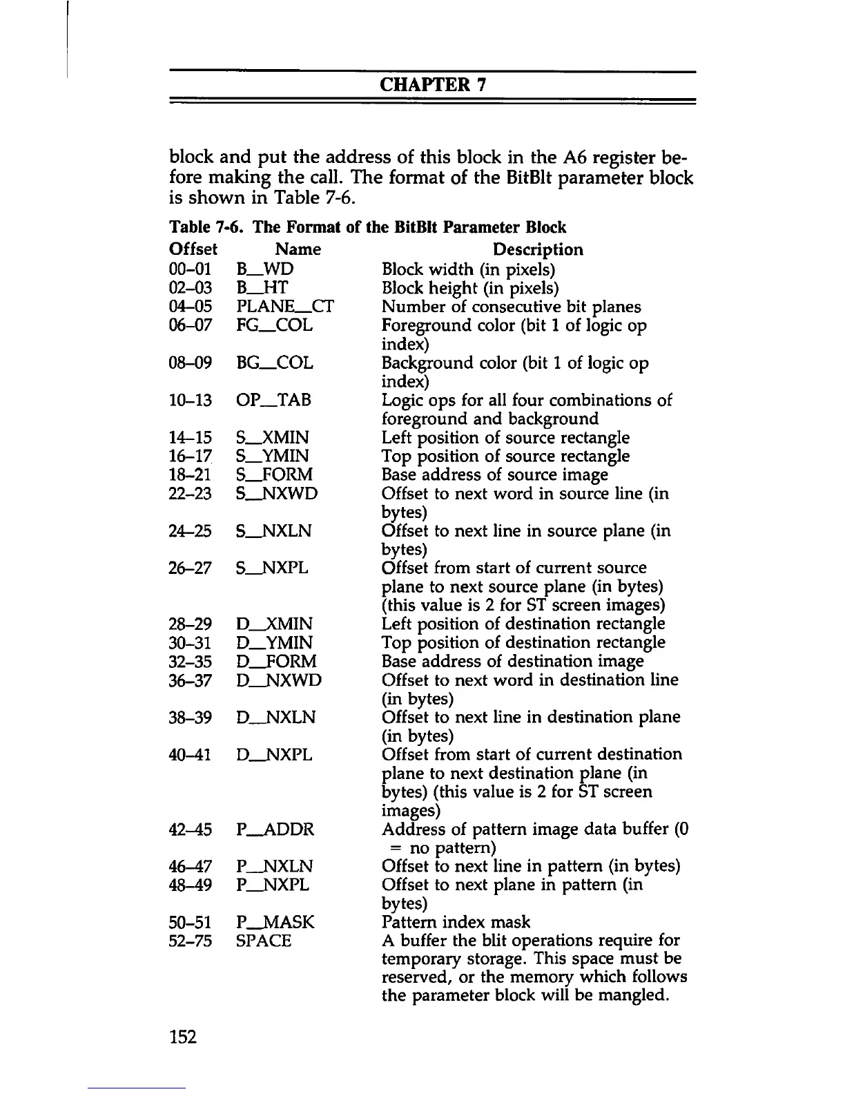
block and put the address of this block in the A6 register be
fore making the call. The format of the BitBlt parameter block
is shown in Table 7-6.
Table 7-6. The Format of the BitBlt Parameter Block
Description
Block width (in pixels)
Block height (in pixels)
Number of consecutive bit planes
Foreground color (bit 1 of logic op
index)
Background color (bit 1 of logic op
index)
Logic ops for all four combinations of
foreground and background
Left position of source rectangle
Top position of source rectangle
Base address of source image
Offset to next word in source line (in
bytes)
Offset to next line in source plane (in
bytes)
Offset from start of current source
plane to next source plane (in bytes)
(this value is 2 for ST screen images)
Left position of destination rectangle
Top position of destination rectangle
Base address of destination image
Offset to next word in destination line
(in bytes)
Offset to next line in destination plane
(in bytes)
Offset from start of current destination
plane to next destination plane (in
bytes) (this value is 2 for ST screen
images)
Address of pattern image data buffer (0
= no pattern)
Offset to next line in pattern (in bytes)
Offset to next plane in pattern (in
bytes)
Pattern index mask
A buffer the blit operations require for
temporary storage. This space must be
reserved, or the memory which follows
the parameter block will be mangled.
24-25 S
_
NXLN
26-27 S
_
NXPL
D_XMIN
D
_
YMIN
D__FORM
D
_
NXWD
38-39 D
__
NXLN
40-41 D
__
NXPL
42-45 P
__
ADDR
46-47 P
__
NXLN
48-49 P
__
NXPL
50-51 P
__
MASK
52-75 SPACE
152