CHAPTER 7
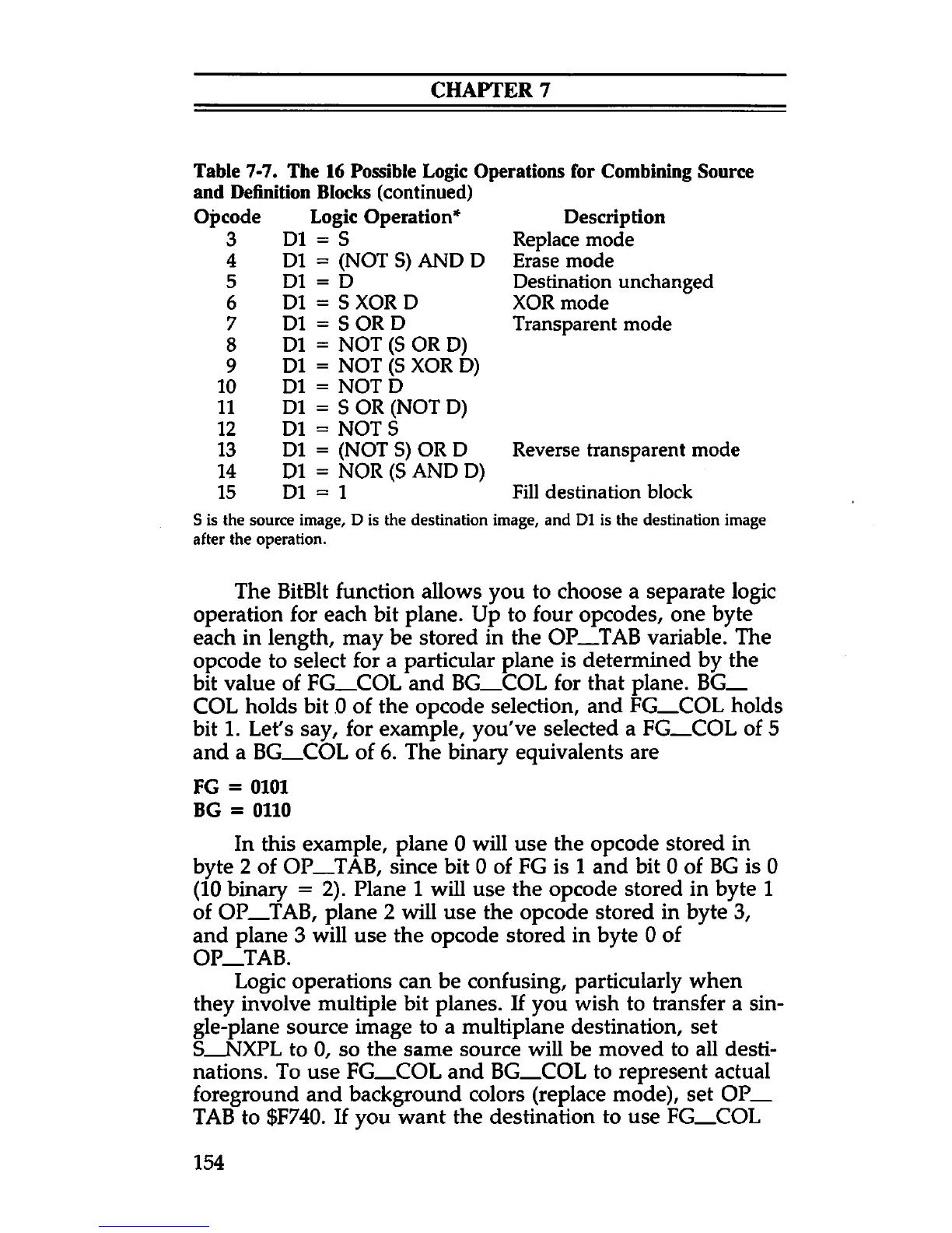
Table 7-7. The 16 Possible Logic Operations for Combining Source
and Definition Blocks (continued)
Opcode Logic Operation*
3
D1 = S
4 D1 = (NOT S) AND D
5
D1 = D
6
D1 = S XOR D
7
D1 = S OR D
8 D1 = NOT (S OR D)
9
D1 = NOT (S XOR D)
10
D1 = NOT D
11 D1 = S OR (NOT D)
12 D1 = NOT S
13
D1 = (NOT S) OR D
14 D1 = NOR (S AND D)
15 D1 = 1
S is the source image, D is the destination
after the operation.
Description
Replace mode
Erase mode
Destination unchanged
XOR mode
Transparent mode
Reverse transparent mode
Fill destination block
image, and D1 is the destination image
The BitBlt function allows you to choose a separate logic
operation for each bit plane. Up to four opcodes, one byte
each in length, may be stored in the OP
__
TAB variable. The
opcode to select for a particular plane is determined by the
bit value of FG
__
COL and BG
__
COL for that plane. BG
__
COL holds bit 0 of the opcode selection, and FG
__
COL holds
bit 1. Let's say, for example, you've selected a FG
__
COL of 5
and a BG
__
COL of 6. The binary equivalents are
FG = 0101
BG = 0110
In this example, plane 0 will use the opcode stored in
byte 2 of OP_TAB, since bit 0 of FG is 1 and bit 0 of BG is 0
(10 binary = 2). Plane 1 will use the opcode stored in byte 1
of OP
__TAB, plane 2 will use the opcode stored in byte 3,
and plane 3 will use the opcode stored in byte 0 of
OP__TAB.
Logic operations can be confusing, particularly when
they involve multiple bit planes. If you wish to transfer a sin
gle-plane source image to a multiplane destination, set
S
__
NXPL to 0, so the same source will be moved to all desti
nations. To use FG
__
COL and BG
__
COL to represent actual
foreground and background colors (replace mode), set OP__
TAB to $F740. If you want the destination to use FG
__
COL
154