XBIOS Graphics and Sound Functions
number. In either case, the function returns the value stored
in the register at the end of the call in the variable regvalue.
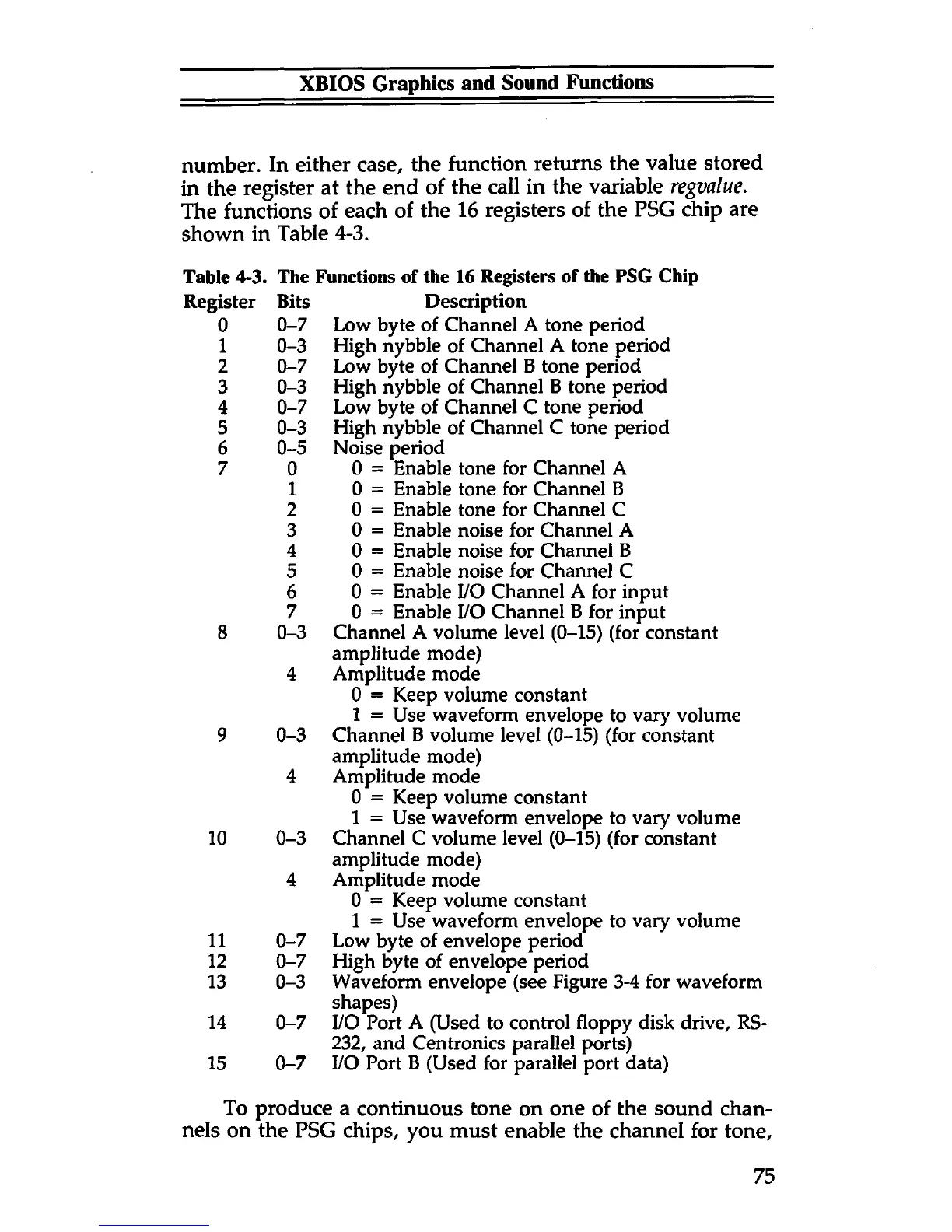
The functions of each of the 16 registers of the PSG chip are
shown in Table 4-3.
Table 4-3. The Functions of the 16 Registers of the PSG Chip
Description
Low byte of Channel A tone period
High nybble of Channel A tone period
Low byte of Channel B tone period
High nybble of Channel B tone period
Low byte of Channel C tone period
High nybble of Channel C tone period
Noise period
0 = Enable tone for Channel A
0 = Enable tone for Channel B
0 = Enable tone for Channel C
0 = Enable noise for Channel A
0 = Enable noise for Channel B
0 = Enable noise for Channel C
0 = Enable I/O Channel A for input
0 = Enable I/O Channel B for input
Channel A volume level (0-15) (for constant
amplitude mode)
Amplitude mode
0 = Keep volume constant
1 = Use waveform envelope to vary volume
Channel B volume level (0-15) (for constant
amplitude mode)
Amplitude mode
0 = Keep volume constant
1 = Use waveform envelope to vary volume
Channel C volume level (0-15) (for constant
amplitude mode)
Amplitude mode
0 = Keep volume constant
1 = Use waveform envelope to vary volume
Low byte of envelope period
High byte of envelope period
Waveform envelope (see Figure 3-4 for waveform
shapes)
I/O Port A (Used to control floppy disk drive, RS-
232, and Centronics parallel ports)
I/O Port B (Used for parallel port data)
To produce a continuous tone on one of the sound chan
nels on the PSG chips, you must enable the channel for tone,
gister
Bits
0
0-7
1
0-3
2 0-7
3
0-3
4 0-7
5
0-3
6 0-5
7
0
1
2
3
4
5
6
7
8
0-3
4
9
0-3
4
10
0-3
4
11 0-7
12 0-7
13 0-3
14 0-7
15
0-7
75