PV
DC
DC
DC
AC
Grid
Battery
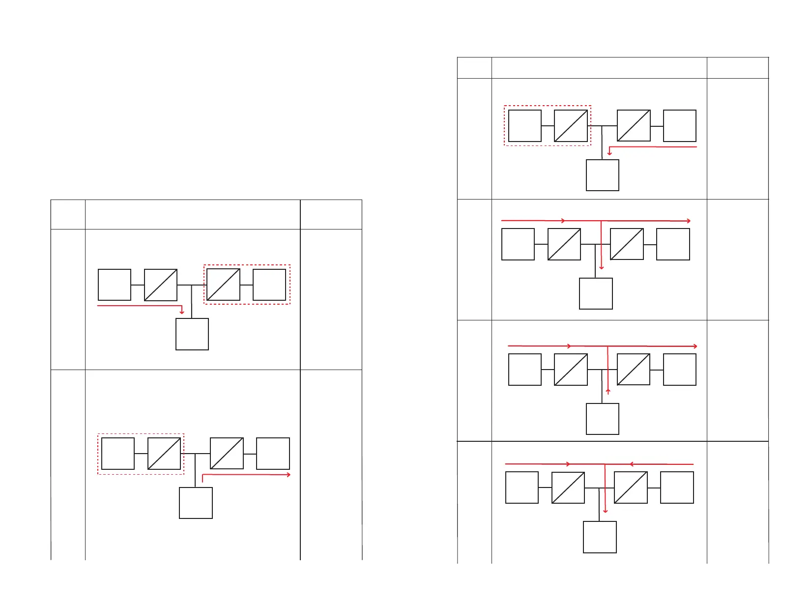
PV power remains 0, all the DC-AC power send to AC
No.
Diagram
Description
K e e p t h e D C -
A C r e c t i f i e r
power at 0, only
m o d i f y P V
power, at th i s
time, PV is fully
charged and AC
has no power
1
Keep PV power
at 0, only modify
t h e D C - A C
power, at th i s
time, the battery
inverts to AC
2
Keep PV power
at 0, and only
m o d i f y t h e
rectifier power.
At this time, the
A C c h a r g e
battery
3
PV power higher
than or equal to
inverte r pow er,
PV convert to AC
i n p r i o r i t y ,
r e m a i n i n g
charge to battery
4
PV power lower
t h a n D C - A C
powe r, PV an d
battery output to
AC together
PV and AC power
charg e b a tt er y
together, when
P V + A C p o w e r
exceeds the max.
charging value,
use PV power to
charge battery in
priority
5
6
3.4.1.5 EMS MODE
Description:
1. In EMS mode, the inverter is controlled by the remote EMS management system, doesn’t have
its own operation logic, and power is controlled by EMS command.
2. In EMS mode, there is no charging curve, only over and under voltage protection value.
3. The power under control includes PV power and DC-AC rectifier power (when not connected
to grid, only PV power can be controlled, and inverter power can be adjusted automatically
according to load). When it is set to inverter, DC output to AC. when it is set to rectifier, AC will
charge the battery.
4. EMS mode does not support manual operation, only remote EMS sending instructions.
Control Description:
PV
DC
DC
DC
AC
Grid
Battery
All PV power charge to battery, DC-AC rectifier power remains 0
No.
Diagram
Description
Battery
PV
DC
DC
DC
AC
Grid
PV power remains 0, all retifier power charge to battery
Battery
PV
DC
DC
DC
AC
Grid
PV power≥DC-AC power
Battery
PV power<DC-AC power
PV
DC
DC
DC
AC
Grid
Battery
PV
DC
DC
DC
AC
Grid
PV power+retify power charge to battery
11 12


 To Next Page