ECO 6 – User and installation manual
Release 5.1 8
The size of the drilling template for the insertion of the display frame varies according to the size of the
selected panel (see reference manuals). The electrical connection between the panel and the controller
must only be carried out using the 4-pin serial cable provided by ATEX. The display panel must be mounted
in a position that is not subjected to shocks, vibrations, splashes of water and in any case where the
temperature and humidity do not exceed the specification values.
The controller must be powered at 230Vac. When inserting fastons or connectors, do not bend the printed
circuit board which could damage or break components. Switch on the power supply for 230 / 110Vac
loads on N = neutral, L = line and PE = ground respecting the positions. The pins of the connectors marked
N are in parallel with each other. The U1-U2-U3-U4-U5-U6 pins report the input phase when the
respective relays are enabled. Using the RL1 - RL6 parameters, the outputs can be configured according
to the required action described in the table on page 9. The board can be fastened using plastic spacers
or using the fixing hooks using the 9 DIN modules support that can be supplied on request.
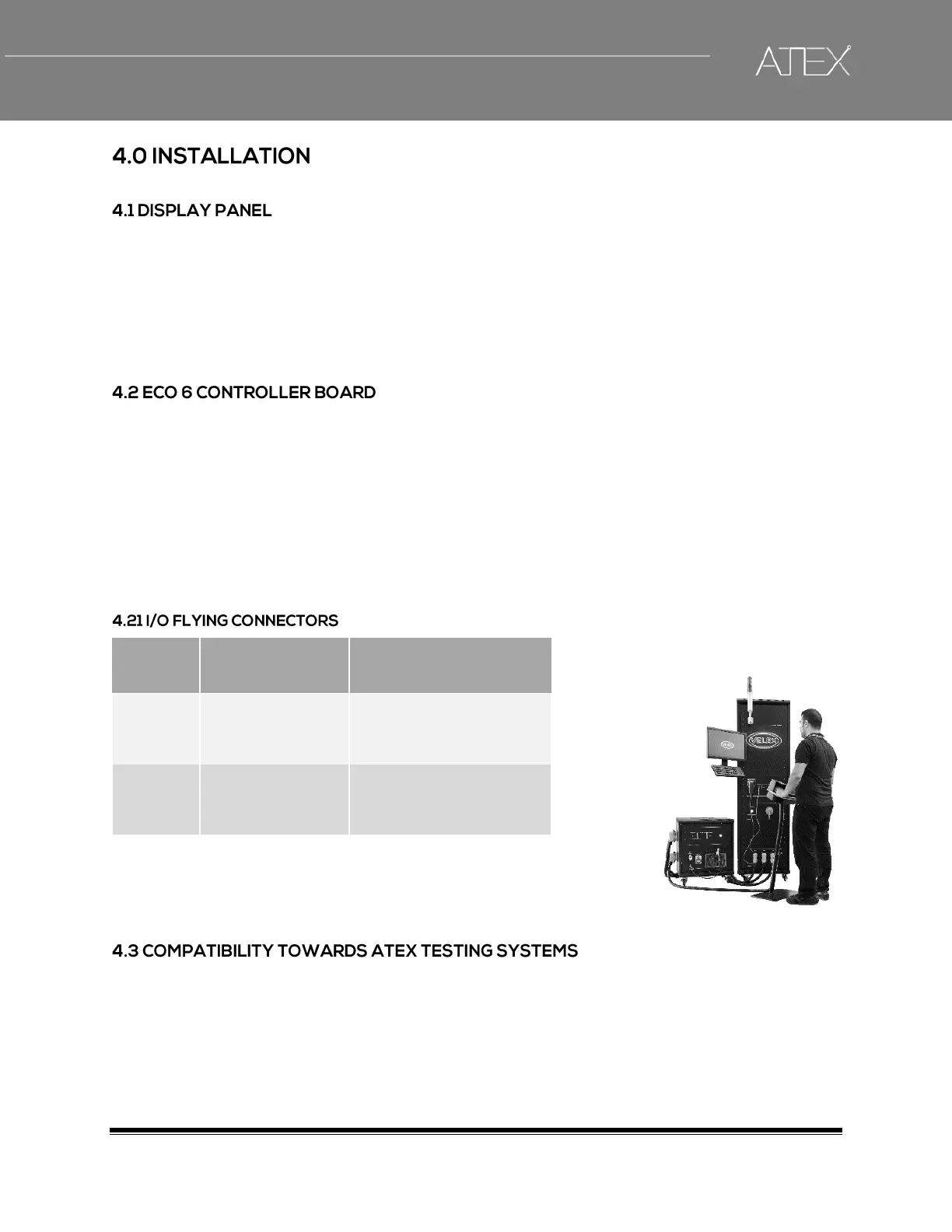
The TOP_FOOD controller board installed on the refrigerating unit and connected to ATEX test systems
via CANBUS allows direct load control and parameter configuration.
 Loading...