82
SL1 DATA LOGGER User Manual Rev. AD
sales.get@athena.euwww.getdata.it
ENGLISH
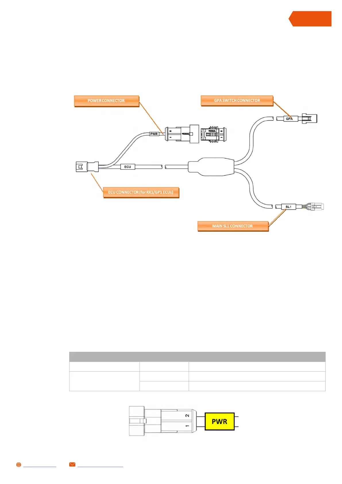
3 MULTILINK WIRING CODE GL-0167-AB
Position of the connectors in the MULTILINK wiring, code GL-0167-AB
• ECU CONNECTOR: Input for the GP1/RX1 ECUs family or LC1-EVO lambda module
(data via CAN Bus)
• GPA CONNECTOR: input for the GPA SWITCH module
• MAIN SL1 CONNECTOR: input for the SL1 Data Logger connection (MAIN connector).
• PWR CONNECTOR: to be used to power the system.
NOTE: all the connected devices will turn on (e.g ECU, SPA SW...)
PWR CONNECTOR PINOUT
CONNECTOR/CABLE PIN DESCRIPTION
PWR
1 Power supply positive
2 Power supply negative (GNDPWR)
 Loading...