www.atkinsonelectronics.com Circuit Board Division
800.261.3602 Revised 05/19
Power Up Initialization Routine
To power up the controller, insert the fuse into the battery wire fuse holder or switch on the circuit
breaker. The controller cycles each LED thru its three colors:
Charge monde & battery status Red, orange & green
Charge type Red, blue & magenta
The controller then checks its voltage inputs, the battery type DIP switches and looks for any flags. The
controller then enters ready mode, re-reading the battery & solar panel voltages, if the solar voltage is
less than 10VDC, it displays the battery status level by blinking the status LED once every 10 seconds:
Green Full
Orange Partial
Red Low
If the solar voltage is greater than 10VDC it turns on the LED to indicate battery level. If the battery
voltage is less than 10.5VDC it blinks the battery status LED red and sets a soft charge flag, blinking the
charge type LED red, and sets the battery equalization flag alternating between red and blue. The
controller then determines if there is enough solar voltage to charge, if the voltage is less than the
minimum voltage for charging, the charge mode LED remains off. Once the solar voltage reaches the
minimum operational voltage it again checks the battery voltage to determine the absorption time, and
checks for a soft charge flag. If the soft charge flag is set, then it enters the charge routine turning on the
charge mode and type LEDs red to indicate it is in a soft/ bulk charge. If the soft charge flag was not set,
then the charge mode LED will be lit red indicating it is in
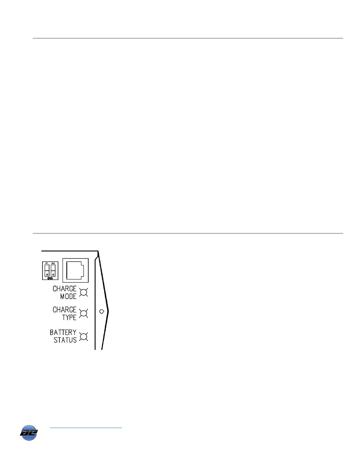
Battery Type Selection Switch
The PVCM40D-MPT’s battery type selection dip
switch is located left of the cat5e jack for the
SEDM6-40 display module.
The PVCM40D-MPT has three bi-color LED’s,
one each for the three following conditions:
Charging mode: Red, orange, green
Charge type: Red, magenta, blue
Battery level status: Red, orange, green
8