This document is an instruction book for Atlas Copco piston compressors, covering various models including LE/LT5, -6, -7, -8, -9, -11, -12, LT530, -730, -930, -1230, LE7N, LE9N, and LE/LT7, -8, -9, -11, -12Pack. It provides comprehensive guidance on safe operation, optimum efficiency, and extended service life for these machines.
Function Description
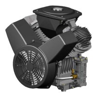
The Atlas Copco piston compressors described are two-cylinder, air-cooled, single-acting units. The LE and LEN models are single-stage compressors, while the LT models are two-stage. LEN compressors are specifically designed to be oil-less, delivering oil-free air.
The compressor block integrates several key components:
- Air intake filter (2) and silencer (3): For filtering incoming air and reducing noise.
- Fan (34): For cooling the compressor.
- Air cooler(s) (25): To cool the compressed air.
- Unloader (22, for LE/LT7 up to -12): A mechanism to relieve pressure during unloaded operation.
- Relief valve (27, for LT7 up to -12): A safety device to protect the LP side of the compressor.
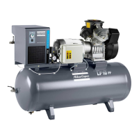
The power pack variants include an electric motor (M), a check valve (8), and an air pressure switch (PSR19). For LE/LT7 up to -12 models, a solenoid valve (Y1) is also included. Complete units are power packs mounted on an air receiver (9) with an air outlet valve (15), pressure gauge (13), safety valve (12), and condensate drain cock (10). Optional sound-insulated hoods are available for Pack units, which enclose the power pack, regulating equipment, and a small air receiver, with hinged top and service panel for easy maintenance.
The air flow system varies slightly between LE/LEN and LT models:
- LE and LEN (Fig. 2a): Air is drawn through the air filter, intake silencer, and inlet valves into the cylinders, compressed, then discharged through delivery valves to a discharge collector and temperature reducer for cooling. The compressed air then passes via a check valve into the air receiver.
- LT (Fig. 2b): Air is drawn through the air filter, intake silencer, and inlet valve into the LP cylinder, compressed, and discharged to an intercooler. The cooled air then flows through a pulsation damper and an inlet valve to the HP cylinder, where it is further compressed and discharged through a delivery valve to a temperature reducer for final cooling before entering the air receiver via a check valve.
The regulating system ensures efficient operation by controlling the motor and air pressure.
- LE/LT5 and -6 (Fig. 2a): Features a check valve (13) and an air pressure switch (PSR19) with a pressure release valve (20) and ON/OFF buttons. The pressure switch also includes an overload relay (e1). It operates by stopping the motor and venting air from the compressor's delivery side when maximum pressure is reached, and restarting when pressure drops to a minimum.
- LE/LT7 up to -12 and LEN (Fig. 2b): Includes a motor starter, air pressure switch (PSR19), solenoid valve (Y1), and unloader (29). When maximum pressure is reached, the pressure switch de-energizes the solenoid valve, allowing compressed air to open the unloader valve, venting air to atmosphere and stopping compression. When pressure drops, the solenoid valve re-energizes, closing the unloader valve and resuming compression.
- Operating Modes: A selector switch (S1) on the motor starter allows selection between semi-automatic and fully automatic operation.
- Semi-automatic: The motor runs continuously, with compressed air either discharged to the receiver or blown off to atmosphere, depending on air consumption. This mode is suitable for steady air consumption and short unloading times.
- Fully automatic: The electric motor stops and restarts based on the pre-set upper and lower limits of the air pressure switch. This mode is ideal for fluctuating air consumption with long interruptions, with a limit of 15 starts per hour.
Important Technical Specifications
The document provides detailed principal data, including:
- Working Pressures:
- LE and LEN: Up to 10 bar.
- LT5 to -12: Up to 20 bar.
- LT530, -730, -930, -1230: Up to 30 bar.
- Motor Starters:
- LE/LT5, -6: Direct-on-line motor starter.
- LE/LT7, -8: May have direct-on-line or star-delta motor starter.
- LE/LT9 to -12 and LE7N/LE9N: Star-delta motor starter.
- FAD (Free Air Delivery): Ranges from 2.17 l/s (LT5, 50 Hz) to 26.0 l/s (LE12, 50 Hz) for 10 bar units, and from 1.98 l/s (LT530, 50 Hz) to 17.0 l/s (LT1230, 50 Hz) for 30 bar units.
- Piston Displacement: Ranges from 3.17 l/s (LT5, 50 Hz) to 57.1 l/s (LE12, 50 Hz) for 10 bar units, and from 3.17 l/s (LT530, 50 Hz) to 28.6 l/s (LT1230, 50 Hz) for 30 bar units.
- Recommended Motor Size: Ranges from 1.5 kW (LE5, LT5, 50 Hz) to 15 kW (LE12, LT12, LT1230, 50 Hz).
- Speed: 1500 r/min (50 Hz) and 1800 r/min (60 Hz) for most models.
- Crankcase Oil Capacity: Ranges from 1.60 l to 5.10 l (not applicable for LEN models).
- Safety Valve Opening Pressure: Ranges from 10.5 bar(e) (LE/LEN models) to 31.5 bar(e) (LT530, -730, -930, -1230).
- Relief Valve Opening Pressure: Ranges from 6.5 bar(e) (LT models) to 12.5 bar(e) (LE12, LE12 Pack).
- Hose Connection: 1/2" B.S.P. (in) for all models.
- Reference Conditions: Inlet pressure 1 bar (absolute), relative air humidity 0%, air inlet temperature 20°C.
- Limitations: Minimum inlet temperature 0°C, maximum inlet temperature 40°C.
Usage Features
- Installation: Compressors should be installed horizontally in a cool, frost-free, and well-ventilated room, with an angular deviation below 15° permissible in any direction. Clean air is essential. Pack units require space for maintenance and clear ventilation openings. A condensate drain facility must be installed downstream.
- Electrical Connections: Must be carried out by a qualified electrician in accordance with local codes. Mains supply voltage and frequency must match motor data plate specifications. An isolating switch and short-circuit protection (fuses or circuit breaker) are required. Earth conductor connection is mandatory.
- Initial Start-up: Involves removing transport brackets, checking electrical installation and thermal overload relay settings, verifying oil level (for non-LEN models), checking fan rotation direction, and adjusting the air pressure switch.
- Starting: For LE/LT, check oil level. Switch on voltage. For LE/LT5, -6, press the start button. For LE/LT7 up to -12 and LEN, select the operating mode via the selector switch. Open the compressor air outlet valve.
- Stopping: For LE/LT5, -6, press the stop button. For LE/LT7 up to -12 and LEN, move the selector switch to "O". Close the air outlet valve and switch off the voltage. If a direct-on-line starter compressor stops due to power failure, pressure must be released manually to prevent restart against back-pressure.
- Regulating System Adjustment: The air pressure switch (PSR19) controls the maximum (stopping) pressure and the pressure drop (difference between stopping and starting pressures).
- MDR5 (Fig. 6): Adjusting knob (1) controls both maximum pressure and pressure difference. Clockwise increases maximum pressure and reduces pressure difference (increases starting pressure). Anti-clockwise lowers maximum pressure and increases pressure difference.
- MDR4 (Fig. 8): Adjusting screw (2) controls maximum pressure (clockwise to raise, anti-clockwise to lower). Adjusting screw (3) controls pressure difference (anti-clockwise to reduce, clockwise to increase).
Maintenance Features
The instruction book provides a detailed preventive maintenance schedule to ensure good condition and long service life. When servicing, all disengaged packings (gaskets, O-rings, washers) should be replaced. Atlas Copco maintenance kits are available.
Daily:
- Check oil level (not on LEN models).
Weekly:
- Drain condensate from the air receiver.
Monthly:
- Operate the safety valve.
- Check that the regulating system operates properly.
- Inspect the air filter; replace if necessary (more frequently in dusty environments).
3-monthly:
- Clean the unit and remove dirt from cooling fins by air jet.
Yearly:
- Test the safety valve.
- Test the relief valve (if provided).
- Replace air filter (intervals vary by model: 400, 500, or 700 running hours).
- Change muffler element on LE/LT7 up to -12 and LEN (1000 running hours).
- Check tension of transmission belt(s) (if equipped with) (1000 running hours).
- Change oil if mineral oil is used (2000 running hours, not on LEN).
- Inspect for carbon deposits in the air receiver; clean if necessary (2000 running hours).
2-yearly:
- Change oil if Atlas Copco approved P.A.O. oil is used (3000 running hours, not on LEN).
- Change check valve on LE/LT5/6 or unloader on LE/LT7 up to -12 and LEN (3000 to 4000 running hours).
- Change valves (4000 running hours).
Lubrication (not for LEN):
- Atlas Copco approved P.A.O. (polyalphaolefine) compressor oil is strongly recommended for excellent operating condition.
- If P.A.O. oil is unavailable, a good-quality mineral motor oil (SAE 10 W 20, API SE-CC, SE-CD or better) can be used, but requires more frequent changes. Mineral oil can be mixed with P.A.O. oil, but this reduces the P.A.O. lubrication properties.
- For extreme operating conditions (high ambient temperature, high loading factor, high pressure), a special diester synthetic lubricant should be used.
- Note: The crankcase is connected to the air intake silencer via a breather valve. Faulty operation or clogging of the calibrated hole can lead to high crankcase pressure and increased oil consumption.
Servicing and Adjustment Procedures:
- Safety Precaution: Always release pressure and isolate the compressor from the mains before starting repair or maintenance.
- Unloader or Check Valve: Replace the assembly after 3000 to 4000 running hours, as dirt, condensate, coke formation, and oxidation can affect proper operation.
- Valves: Faulty valves must be replaced immediately. It is highly recommended to replace valves and gaskets each time cylinder heads are disassembled to prevent accelerated wear. Instructions for replacing valve disks are provided, including steps for removing and installing components like the fan guard, cylinder head cover, outlet/inlet caps, springs, valve guards, valve disks, and valve seats, along with guidance on using new joints and O-rings.
- Air Filter: Never remove the element while the compressor is running or use damaged elements. Servicing involves unscrewing the cap, lifting off the cover and element, cleaning the filter chamber, and installing a new element.
- Safety Valve (12-Figs. 1): Must be tested yearly and replaced if it does not open at the correct pressure. No adjustments are allowed. Testing involves closing the air outlet valve, depressurizing, starting the compressor, stopping it, increasing the stopping pressure via the air pressure switch, and then restarting with the outlet valve slightly open to check the safety valve's operation.
- Relief Valve (27-Figs. 1) (only LT): Protects the LP side of the compressor and must be tested yearly. Testing involves removing the relief valve, plugging its opening, replacing the air receiver's safety valve with the relief valve, and testing it at increasing air receiver pressure.
Problem Solving:
A comprehensive problem-solving table is included, listing common issues, possible faults, and suggested remedies. Examples include:
- Insufficient air pressure: Could be due to air leaks, choked air filter, incorrectly set air pressure switch, or damaged valves.
- Unit does not speed up: Possible causes include voltage drop at motor terminals, malfunctioning pressure release valve, or jammed unloader plunger.
- Air receiver pressure rises above maximum and causes safety valve to blow: Could be due to an incorrectly set or out-of-order air pressure switch, defective solenoid valve, or jammed unloader plunger.
- Thermal overload relay cuts out during starting or operation: Possible causes include an incorrectly set overload relay, interrupted mains supply line, voltage variations, high ambient temperature, or motor/compressor failure.
- High oil consumption: Could be due to overfilling the crankcase, malfunctioning breather valve, or worn piston rings.
The manual emphasizes the importance of reading the book before operation, keeping it available for operators, recording operating data, and contacting Atlas Copco for repairs by trained personnel.