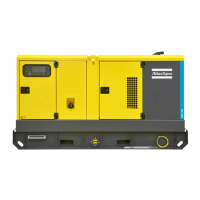
Dual frequency with electronic speed control (DF)
The “Dual frequency with electronic speed control” option
allows the unit to work at 50 Hz or at 60 Hz with an accuracy
of ±0.25 % at constant load. The frequency selection is done
by means of switch S11.
F11 ...Fuse
Interrupts the power supply towards the speed or frequency
controller.
R11 ...Supply voltage adjust potentiometer
Allows to adjust the output voltage.
S11 ...Frequency selector switch (50 Hz / 60 Hz)
Allows to choose the frequency of the output voltage: 50 Hz or
60 Hz.
Changing the output frequency is only allowed after shutdown.
After changing the output frequency, adjust the output voltage
by means of potentiometer R11 to the required value.
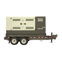
Single frequency with electronic speed control (SF)
The “Single frequency” option provides an electronic speed
controller which makes sure that the output frequency of the
generator is 50 Hz with an accuracy of 0.25 % at constant
load.
F11 ...Fuse
Interrupts the power supply towards the speed or frequency
controller.
R11 ...Supply voltage adjust potentiometer
Allows to adjust the output voltage.
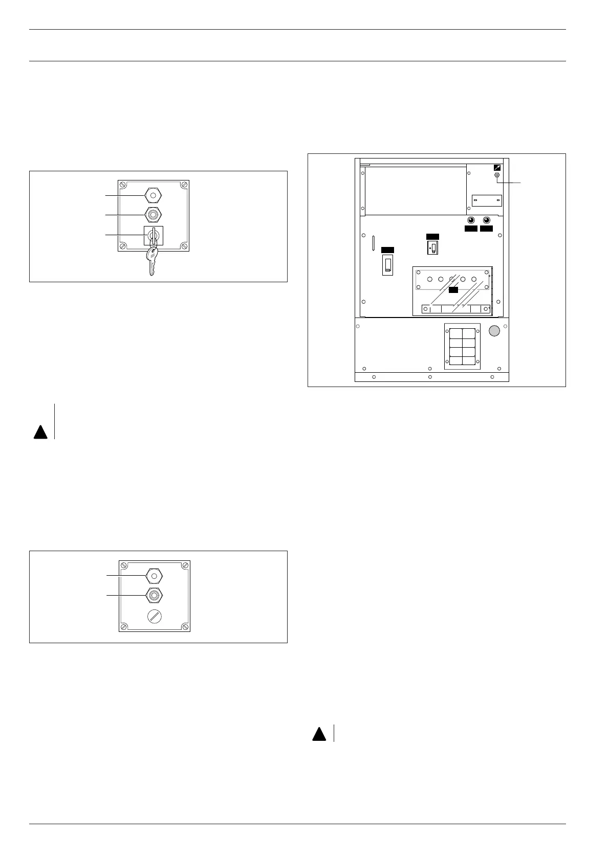
Dual voltage (DV)
The “Dual voltage” option allows to select a high (3-phase,
e.g. 400 V) or a low (3-phase, e.g. 230 V) output voltage.
Q1.1..Circuit breaker for low voltage, high current
Interrupts the low voltage power supply towards X1 when a
short-circuit occurs at the load side or when the overcurrent
protection (250 A) is activated. It must be reset manually after
eliminating the problem and after each start.
Q1.2..Circuit breaker for high voltage, low current
Interrupts the high voltage power supply towards X1 when a
short-circuit occurs at the load side or when the overcurrent
protection (145 A) is activated. It must be reset manually after
eliminating the problem and after each start.
H1.1..Low voltage indication lamp
Indicates that the low voltage circuit breaker Q1.1 can be
switched on.
H1.2..High voltage indication lamp
Indicates that the high voltage circuit breaker Q1.2 can be
switched on.
R11 ...Output voltage adjust potentiometer
Allows to adjust the output voltage.
Circuit breakers Q1.1 and Q1.2 cannot be switched on at the
same time. This is prevented by means of the auxiliary
voltage selection relays K1 and K2 (refer to the circuit
diagram).
The selection of high or low voltage is done by means of
connections on the terminal board of the alternator.
Changing the output voltage is only allowed after shutdown.
16
QAS108 Pd(S) Mk II
 Loading...