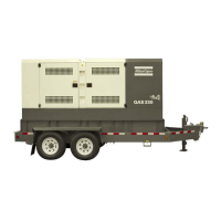
Extended control module
The standard control module is replaced by an extended
module wich allows more detailed control of the unit.
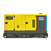
The controls and indicators on the AMF control module are:
L1 .....Mains available
Lights up when the mains is available.
L2 .....Mains on load
Lights up when the mains supplies power towards the load.
L3 .....Mains failed
Lights up when a failure occured on the mains.
L4 .....Plant available
Lights up when the generator is running.
L5......Plant on load
Lights up when the generator supplies power towards the
load.
L6......Plant fail
Lights up when a failure occured on the generator.
L7 .....Start fail
Indicates that four start attempts were not sufficient to start up
the engine.
L8 .....Undervoltage shutdown
Lights up when AC input interruption or failure was the cause
of shutdown.
L9 .....Overspeed shutdown
Lights up when the engine’s speed has exceeded 115% of the
nominal speed. The nominal speed is determined by means of
the dipswitch S8 at the back of the control module.
L10 ...Engine coolant temperature shutdown
Lights up when the high engine coolant temperature was the
cause of shutdown.
L11 ...Engine oil pressure shutdown
Lights up when the low oil pressure was the cause of
shutdown.
L12 ...Charge fail indicator
Goes out after starting, indicating that the alternator is
charging. A failing alternator however will not shut the engine
down.
ST .....Starter switch
P1 : the generator starts immediately. The load will be
transferred if a mains failure occurs.
P2 : the generator will never start.
P3 : the generator will start when the remote start/stop contact
is closed.
P4 : the generator will take over when a mains failure occurs.
P5 : the generator will not start when a mains failure occurs.
Nevertheless, the mains remains monitored and the mains
contactor will trip in case of a mains failure.
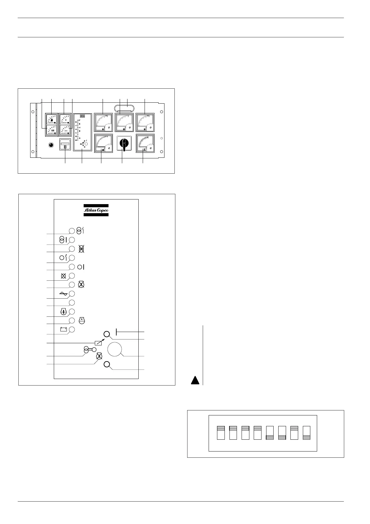
Besides dipswitch S8, located at the back of the control
module and used for the selection of the nominal speed
(50 Hz or 60 Hz), dipswitch S1 can be used for enabling or
disabling a spare shutdown contact.
The contactors between the mains, the unit and the load are
not included in the option but should be sized according to
the load. Nevertheless, they are also available as sales kit at
Atlas Copco. Refer to circuit diagram 9822 0773 55 of the
“Automatic mains failure” option for the correct connection.
For correct functioning of the module, the DIP switches at the
back of the module should be positioned as follows:
20
QAS108 Pd(S) Mk II
 Loading...