20
Instruction Manual
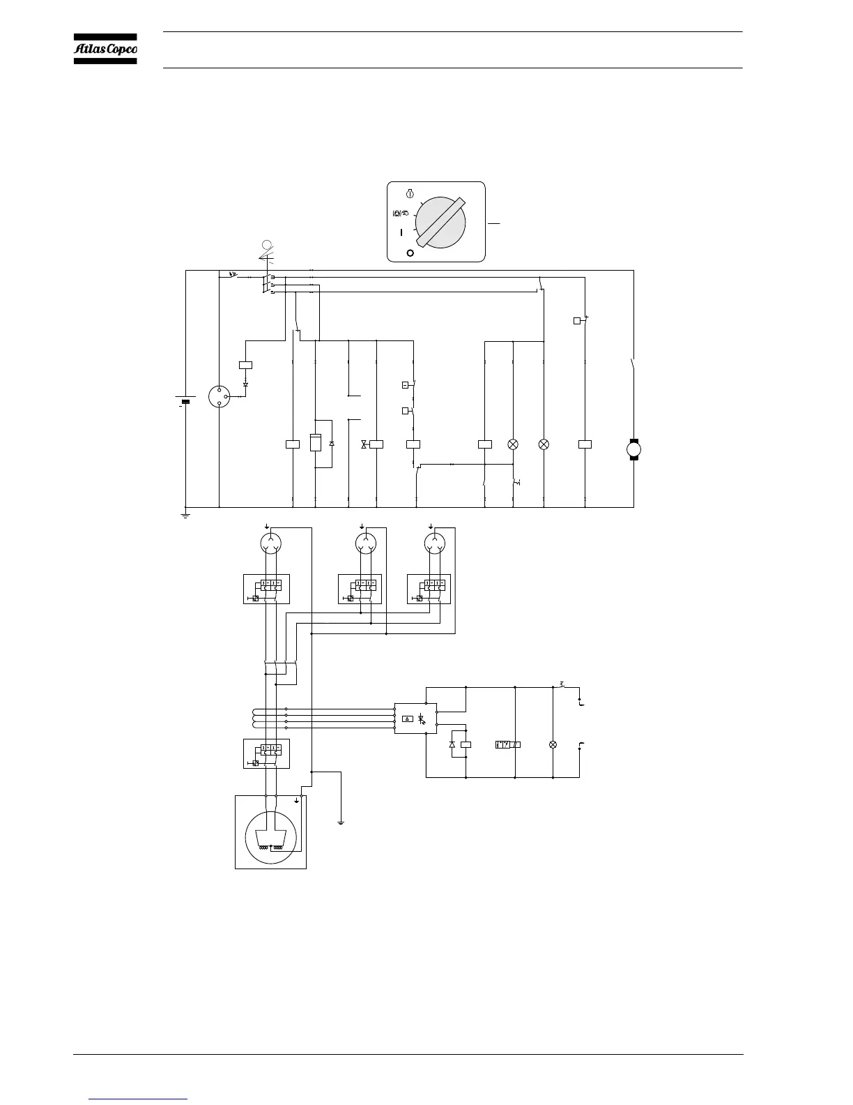
2.8.2 CIRCUIT DIAGRAM XAS 47 DDG -
XAS 90 DD7G (G
ENERATOR DDG 110V
WITHOUT AUTOMATIC CONTROL SYSTEM)
(Not on HardHat)
The compressor is equipped with a negative earthed system.
Fig. 2.6 Circuit diagram (No. 9822 0797 01 + No. 9822 1055 27)
For location of relais K1, K2, K3, K4, see paragraph 2.8.1
D1 Diode
F1 Circuit Breaker (10A)
G1 Alternator
G2 Battery
G3 Generator
H1 Temperature Alarm Lamp
H2 General Alarm Lamp
H3 Lamp (Power ON)
K0 Starter Solenoid (part of M1)
K1 Shut-down Relay
K2 Blocking Relay
K3 Override Start Relay
K4 Start Relay
K5 Contactor
M1 Starter Motor
N13 Earth faultcurrent relay
P1 Hourmeter
Q1 Main circuit breaker 2-pole
Q2 Circuit breaker 2-pole
Q3 Circuit breaker 2-pole
Q4 Circuit breaker 2-pole
S1 Contact Switch (Off-On-
Override-start)
S2 Temperature Switch Engine
S3 Oil Pressure Switch Engine
S4 Lamptest Switch
S5 Temperature Switch
Compressor
S7 Switch (Generator-compressor)
T13 Current transformer for N13
V1 Diode
V2 Diode
X1 Socket outlet
X2 Socket outlet
X3 Socket outlet
Y1 Fuel solenoid Valve
Y2 Solenoid valve (Generator
action)
 Loading...