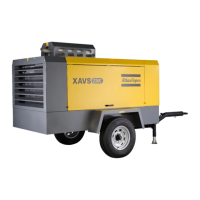
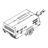
Do you have a question about the Atlas Copco XAS 90 DD7 and is the answer not in the manual?
Lists general safety rules for operating, maintaining, and repairing Atlas Copco equipment.
Details safety procedures for moving and setting up the compressor unit.
Outlines crucial safety measures for operating the compressor safely and preventing hazards.
Covers safety guidelines for personnel performing maintenance and repair tasks on the unit.
Presents the standard electrical circuit diagram for the compressor unit.
Shows the electrical circuit diagram for models with a 110V generator without automatic control.
Provides the electrical circuit diagram for models with a 110V generator and automatic control.
Details the circuit diagram for models with a 230/400V IT generator without automatic control.
Presents the circuit diagram for models with a 230/400V IT generator and automatic control system.
Shows the electrical circuit diagram for models with a 230V, 6 kVA generator.
Covers the procedures for starting and stopping the compressor.
Details the step-by-step procedure for starting the compressor when equipped with the cold start option.
Provides the step-by-step instructions for starting the compressor without the cold start option.
Describes common faults and the protective devices that shut down the compressor.
Explains the functionality of the optional generator.
Explains the operation of the 110V generator without automatic control for portable compressors.
Details the operation of the 110V generator with an automatic control system.
Describes the function of 230/400V and 230V 3-phase generators without automatic control.
Explains the operation of 230/400V and 230V 3-phase generators with automatic control.
Provides a detailed schedule of recommended preventive maintenance tasks and intervals.
Covers the procedures for changing engine and compressor oil and filters.
Details the steps for changing the compressor oil and oil filter, including draining and refilling procedures.
Details the procedure for adjusting the continuous regulating system to set working pressures.
Specifies the settings for engine and compressor shutdown switches and safety valves.
Lists key specifications for the compressor and engine, including operating conditions and limitations.
| Model | XAS 90 DD7 |
|---|---|
| Engine | Deutz diesel engine |
| Typical sound level (LWA) | 95 dB(A) |
| Noise Level | 95 dB(A) |
| Working Pressure | 7 bar (102 psi) |


