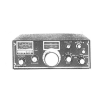
Figure 2-3. Deluxe Plug-in Mobile Mounting Kit Installation
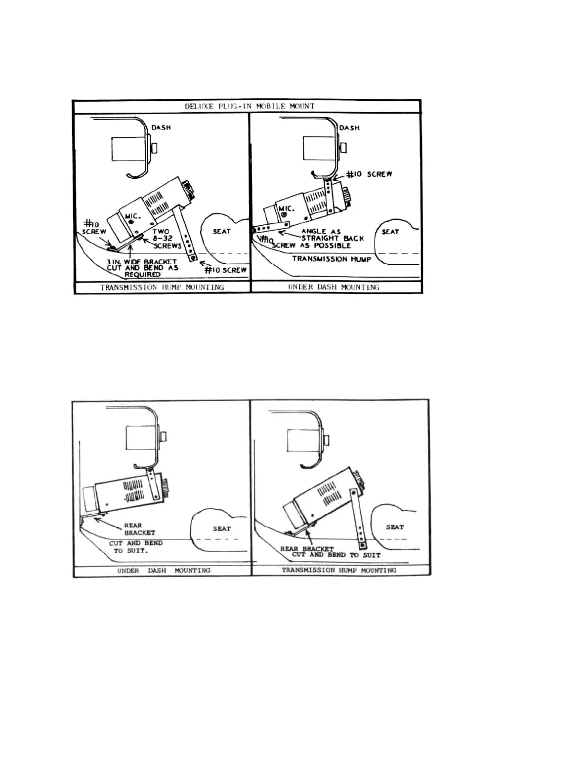
2-24. MOBILE BRACKET KIT (MBK). This kit includes: One 9-inch and two 12-inch cadmium plated steel
mounting bars with screws. Figure 2-4 illustrates how the transceiver can be hung under the dash, or mounted over
the transmission hump. Each installation is different, so this must be left to the individual. Consult your dealer or
friends with mobile experience if need be. The brackets can be cut easily and bent as required. The smaller No.
6x3/4 inch screws are for attaching the brackets to the sides or bottom of the transceiver. They will replace the No.
4x1/4 inch screws that came in the transceiver, thus allowing for the 1/8 inch thickness of the bracket. The No. 6
screws will make the brackets more secure than the original No. 4's would. The No. 14 screws are for securing the
brackets to the under side of the dash, or to the transmission hump. No. 10 screws are also furnished in case the
No. 14 screws are too large.
Figure 2-4. Mobile Bracket Kit Installation
2-25. INSTALLING D.C. POWER CABLE. The power cable should be run from the transceiver, through the
bulkhead, and connected as close to the battery as is practical. The best way is to connect directly to the battery
posts. Drill and tap into the lead terminal posts for 10-32 machine screws, and secure No. 10 terminal lugs under
these screw heads. The advantage of doing this is that even if the battery clamps work loose, it will not
11
 Loading...