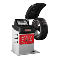
The 501 Atlas Alignment Machine is a sophisticated piece of equipment designed to facilitate precise vehicle wheel alignment. This guide outlines the unpacking, setup, and initial operational steps to get your new machine running quickly and efficiently. The core philosophy behind this machine's design is ease of use and rapid deployment, minimizing the need for complex software installations or extensive calibration procedures right out of the box.
Function Description:
The primary function of the 501 Atlas Alignment Machine is to measure and adjust the alignment angles of vehicle wheels, ensuring optimal handling, tire wear, and fuel efficiency. It achieves this through a combination of a dedicated computer system, wireless sensors (referred to as "heads"), and a comprehensive database of vehicle specifications. The machine is designed to be largely self-contained, with its essential components integrated into a mobile cabinet, making it suitable for various workshop environments. The wireless communication between the sensors and the main unit enhances flexibility and reduces cable clutter in the work area. The system's "identity" and database are stored on a dedicated card, which is crucial for its operation, ensuring that the machine always has access to the necessary vehicle data for accurate alignment procedures.
Usage Features:
Upon receiving your 501 Atlas Alignment Machine, the setup process is streamlined to get you operational as quickly as possible.
- Out-of-the-Box Readiness: One of the most significant usage features is that the machine is ready to operate immediately after unpacking. There's no need for software installation, complex calibration, or any other preliminary steps beyond connecting the necessary cables. This "plug-and-play" approach significantly reduces setup time and allows technicians to begin alignment tasks almost instantly.
- Cable Installation: The initial setup involves connecting several cables to the back of the computer unit. These include USB cables for peripherals, a VGA cable for the monitor, a USB cable for the printer, and the main power cable. The instructions emphasize the simplicity of these connections, ensuring that even users with minimal technical expertise can complete the setup.
- Cabinet Access: To access the internal components for cable connections, users will need to unscrew four screws on the front panel and four screws on the back cover of the machine. A crucial note is provided regarding the back cover, which has a ground wire attached. Users are advised to be careful not to pull this wire loose when setting the cover aside, highlighting a small but important detail for safe handling.
- Monitor Installation: The monitor, shipped in a separate box, is mounted to an existing bracket on the cabinet. The process involves using four small Allen screws provided with the hardware. The angle of the monitor can be adjusted by loosening larger Allen head screws, tilting it to the desired position, and then tightening them back. This ergonomic feature allows technicians to customize the viewing angle for comfort and visibility during operation.
- Data Storage and Identity Card: The machine utilizes a unique "identity" card, which contains the aligner's essential database. This card must be inserted into a mounted card reader and remain there at all times for the machine to function properly. This design ensures that the machine consistently accesses the correct data for alignment procedures. The importance of not losing this card is heavily emphasized, underscoring its critical role in the machine's operation.
- Printer Connection: The printer is the final peripheral to be connected. This involves a USB cable running from the computer to the back of the printer and a power cable from the power strip (located at the back of the unit) to the printer. An adapter is supplied, though it's noted that it may not be needed in most cases, simplifying the power connection process.
- Wireless Head Charging: The 501 model features wireless communication for its sensor heads during normal operation. However, for charging, users need to plug the charging ports into the bottom of the sensors. This dual system (wireless for operation, wired for charging) ensures both operational flexibility and reliable power management for the sensors. The connection process for charging is straightforward, involving plugging a specific cable into the sensor's charging port.
Maintenance Features:
While the manual primarily focuses on initial setup, several points touch upon aspects relevant to long-term use and potential maintenance.
- Software and Calibration: The explicit statement that "There is no need to install software, calibrate, or do anything other than proceed with cable installation" implies that the machine comes pre-calibrated and with all necessary software pre-loaded. This significantly reduces the ongoing maintenance burden related to software updates or periodic calibrations, which are often required for other complex machinery.
- Remote Support Preparedness: The inclusion of a disk and a flash drive with the computer, to be stored in a safe place, is a forward-thinking maintenance feature. These items are specifically designated for use during remote support sessions for "memory purposes." This indicates that the manufacturer has provisions for remote diagnostics and troubleshooting, allowing for efficient resolution of potential issues without requiring an on-site technician. By having these tools readily available, users can facilitate quicker support and minimize downtime.
- Critical Identity Card Management: The "identity" card, which holds the aligner's database, is a critical component. The strong emphasis on keeping this card inserted at all times and not losing it highlights its importance for the machine's functionality. While not a direct maintenance task, proper management of this card is essential for continuous operation and avoids potential data loss or operational interruptions that would require support to resolve.
- Robust Design for Connectivity: The design of the machine, with internal components accessible by removing panels, suggests a modular approach that could simplify future maintenance or upgrades if needed. The clear instructions for accessing these areas indicate that the design anticipates the need for internal access, even if only for initial setup.
- Component Variation: The note that "Printer and PC may vary in style or model" suggests a degree of flexibility in component sourcing, which can be beneficial for long-term support and replacement part availability. While the core functionality remains consistent, the ability to integrate different models of standard components can simplify maintenance logistics.
In summary, the 501 Atlas Alignment Machine is designed for efficiency, ease of use, and reliable performance, with a strong emphasis on getting the user operational quickly and providing clear guidance for setup and essential operational procedures. Its wireless sensor technology, pre-configured software, and remote support readiness contribute to a user-friendly experience and simplified maintenance.