Do you have a question about the Atlas CP700 and is the answer not in the manual?
Warning about high sound pressure levels and potential permanent hearing damage.
Caution regarding shock risk at speaker terminals; power off for connections.
Ensuring adequate airflow is crucial for amplifier operation and heat dissipation.
Guidelines for secure installation and support within equipment racks.
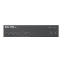
Overview of the Atlas Sound CP700 dual channel power amplifier.
Details features like independent power supplies, soft clip limiter, and cooling.
Lists common uses such as paging, BGM, and sound reinforcement.
Describes the power switch and associated LEDs for power and signal status.
Explains the function of the Protect and Limit LEDs on the front panel.
Details the XLR and barrier strip inputs for audio sources.
Covers speaker outputs, mode selection switch, and gain controls.
Instructions for connecting balanced audio sources via XLR or barrier strip.
Instructions for connecting unbalanced audio sources, including jumper requirement.
Explains how to select operating modes using the rear panel switch.
Wiring for direct coupled outputs into 2, 4, and 8 Ohm loads.
Wiring for 25V, 70.7V, 100V, 140V, and 200V systems.
| Power Output | 700W |
|---|---|
| Channels | 1 |
| Frequency Response | 20 Hz - 20 kHz |
| Type | Power Amplifier |
| Power Output (per channel) | 700W @ 4 Ohms |
| Signal-to-Noise Ratio | >100dB |
| Input Sensitivity | 1.4V |
| Damping Factor | >200 |
| Input Impedance | 10 kOhms |