Quick Start Steps 5
Cyclops
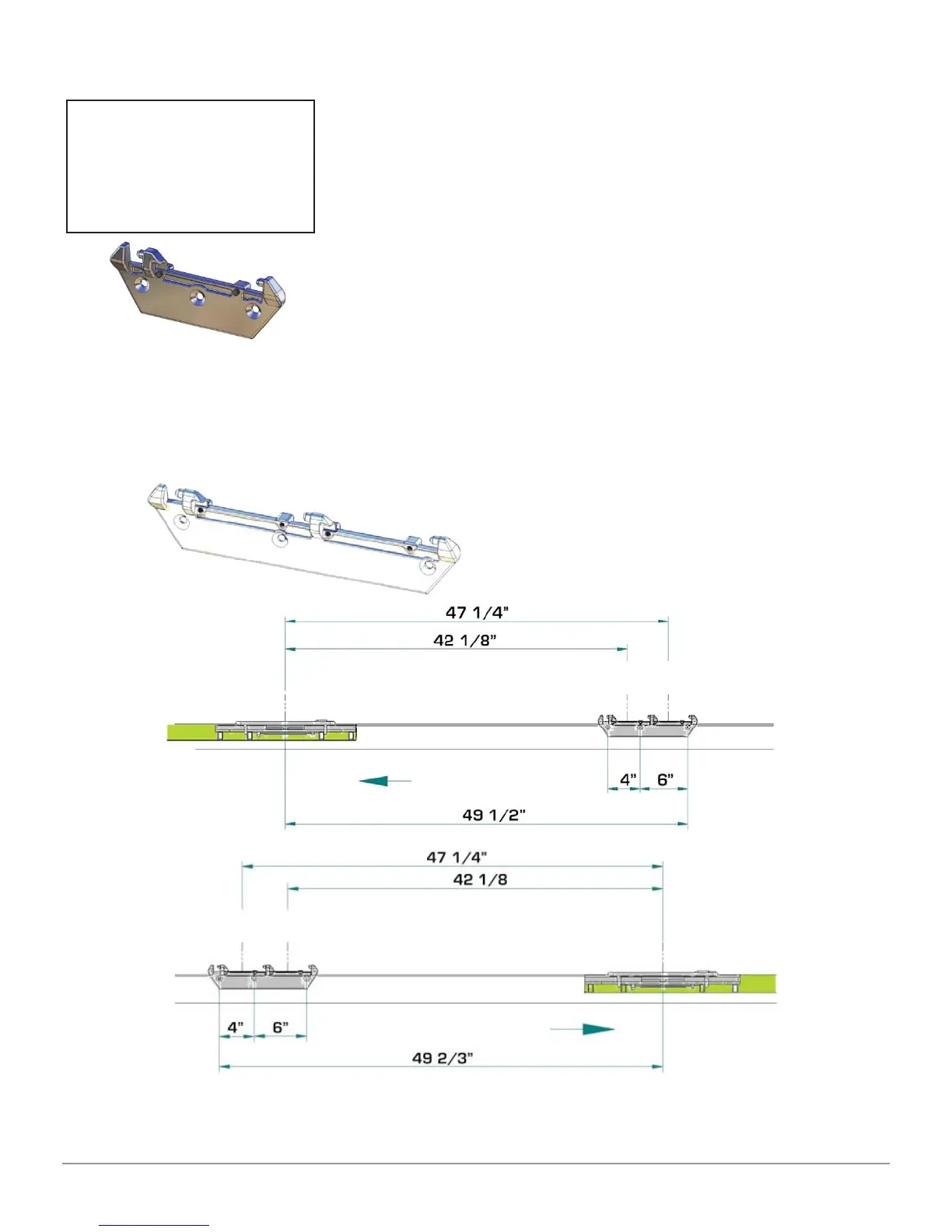
Mounting Head’s Brackets
Using the support of fi gure 1:
Place the Turn Table properly as per the position shown in
the manual (in the backward Turn Table place).
Take the measures to fi x the measuring heads supports as
indicated in the service manual.
Distance between the center of the Turn Table and the fi rst
hole of the heads support:1135 mm for the left side and
1140 mm for the right side with respect to the drive-in
direction of the vehicle.
Using the heads support as a template, mark the spot
where drilling, drill with a drill bit for steel diameter of 6.7
mm and thread M8.
The support of fi gure 2 must be fi xed using the measurements shown below
Figure 2 – New measuring heads support
Using the heads support as a template, mark the spot where drilling, drill with a
drill bit for steel diameter of 6.7 mm and thread M8.
Figure 1 - Support heads
used up to 31/12/2014
Remove from the
boxes containing the
measuring heads
the 2 supports to be
screwed in the lift.
Measure for the Left side ramp
Drive-in Direction
Measure for the Left side ramp
Drive-in Direction
 Loading...