HyHydrdrauaulilic sc sysystetem / Rm / Repepaiair ir insnstrtrucuctitionons / s / InInststalallalatition on ininststruructctioion fn for or pipipe pe cocoupuplilingngss 8.8.3535
InstallaInstallation instruction for tion instruction for pipe couplingspipe couplings
TTo achieve a safe o achieve a safe and tight connection when installing pipe couplings in and tight connection when installing pipe couplings in the hydraulicthe hydraulic
system, the following points should be system, the following points should be taken into consideration:taken into consideration:
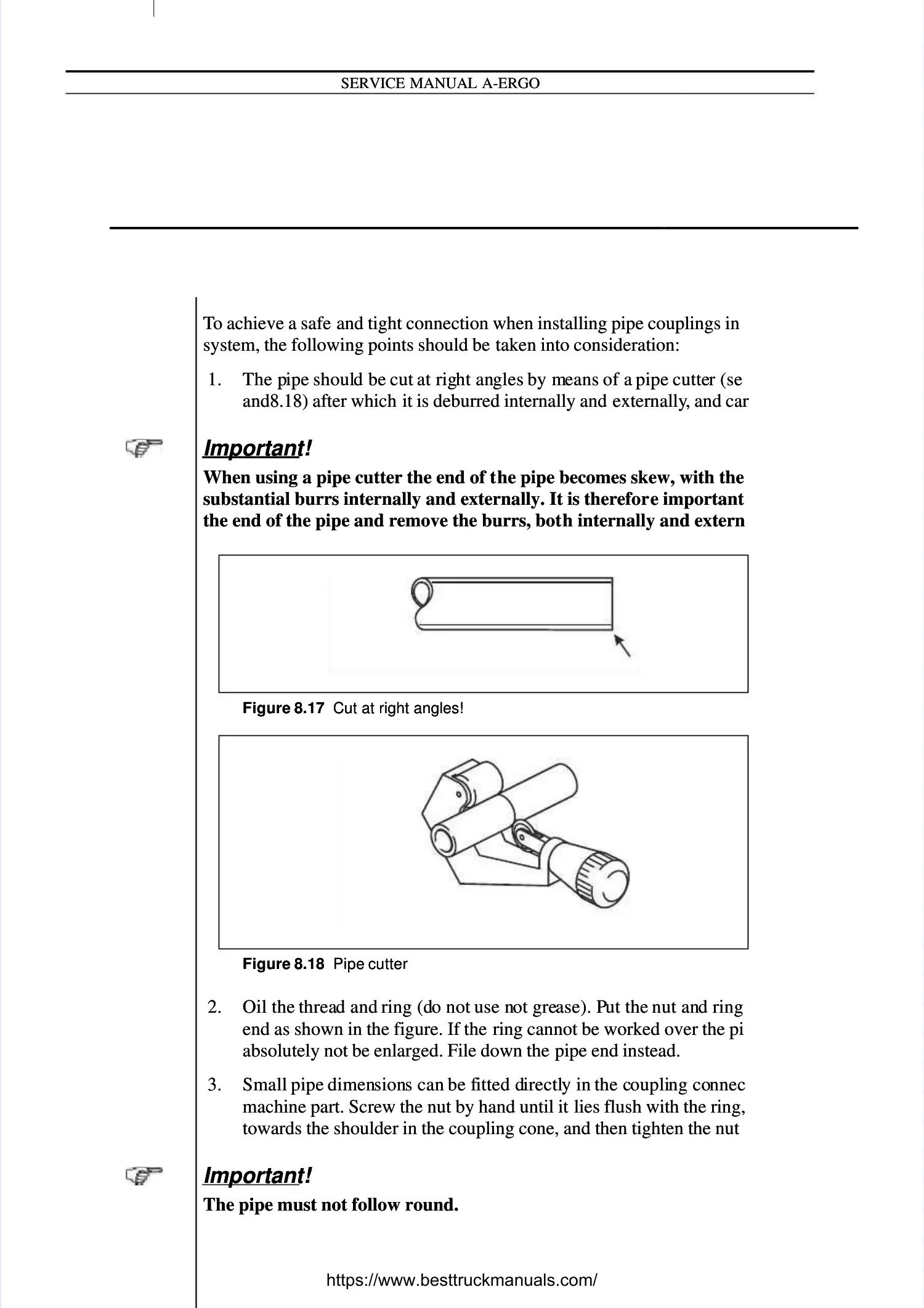
1.1. The pThe pipe ipe shoulshould be d be cut cut at rigat right anht angles gles by mby means eans of a of a pipe pipe cuttecutter (ser (see figue figurere8.178.17
andand8.188.18) after which ) after which it is deburred internally and it is deburred internally and externallyexternally, and carefully cleaned., and carefully cleaned.
Important!Important!
When using a pipe cutter the end of tWhen using a pipe cutter the end of the pipe becomes skew, with the formation ofhe pipe becomes skew, with the formation of
substantial burrs internally and externally. It is thereforsubstantial burrs internally and externally. It is therefore important to straightene important to straighten
the end of the pipe and remove the burrs, botthe end of the pipe and remove the burrs, both internally and externally.h internally and externally.
2.2. Oil the Oil the threathread and d and ring (dring (do not o not use nuse not greot grease). Pase). Put the ut the nut annut and ring d ring over thover the pipe pipee
end as shown in the figure. If the end as shown in the figure. If the ring cannot be worked over the pipe end it mustring cannot be worked over the pipe end it must
absolutely not be enlarged. File down the absolutely not be enlarged. File down the pipe end instead.pipe end instead.
3.3. Small Small pipe pipe dimendimensionsions can s can be fbe fitted ditted directlirectly in y in the cthe couplioupling cong connecnnected ted to theto the
machine part. Screw the nut by hand until it machine part. Screw the nut by hand until it lies flush with the ring, lies flush with the ring, press the pipepress the pipe
towards the shoulder in the coupling cone, and then tighten the nut a ¾ turn.towards the shoulder in the coupling cone, and then tighten the nut a ¾ turn.
Important!Important!
The pipe must not follow round.The pipe must not follow round.
Figure 8.17Figure 8.17 Cut at right angles!Cut at right angles!
Figure 8.18Figure 8.18 Pipe cutterPipe cutter
hydraulror 1.epshydraulror 1.eps
!
!
hydraulror 2.epshydraulror 2.eps
 Loading...