21
4929B–AUTO–01/07
ATA6264 [Preliminary]
Necessary for operation:
V
EVZ
= 5.5V to 40V or V
K30
= 5.5V to 40V, V
K15
> 3V, V
VINT
= 3.7V to 5.47V
Operating conditions of all other supply pins:
V
VSAT
, V
VPERI
and V
VCORE
are within functional range limits, T
j
= –40°C to 150°C
Other pins:
As defined in Section 4. ”Functional Range” on page 8.
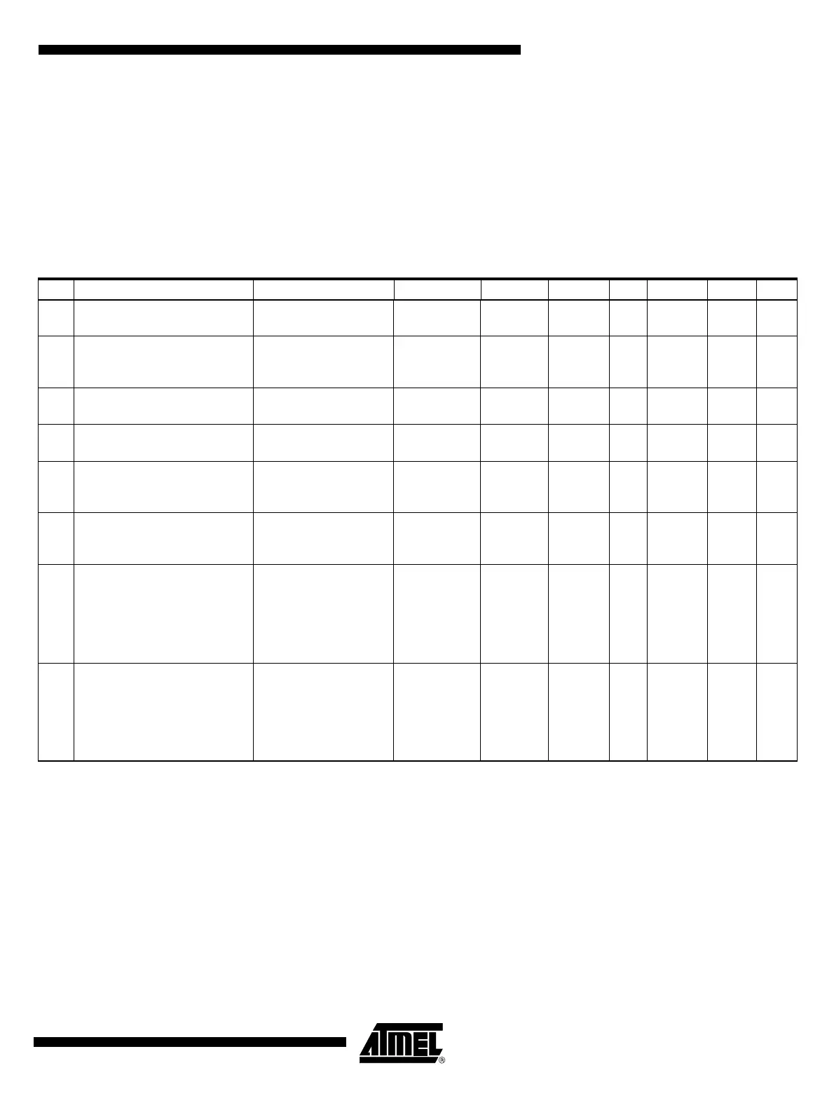
Table 7-1. Electrical Characteristics – Charge Pump
No. Parameters Test Conditions Pin Symbol Min Typ. Max. Unit Type*
6.11 Supply current at pin CP
CP off, supply of
internal circuitry
CP I
CP
050µAA
6.12
Time between wrong CP-OUT
voltage and valid data in status
register
CP-OUT t
d
050µsA
6.13
Current limitation at pin
CP-OUT
CP-OUT I
CP-OUT
–0.8 –4.2 mA A
6.14
Voltage difference V
CP
– V
EVZ
for detecting wrong CP
Note: Threshold is in
the range of 5V to 7V
CP V
Diff
5VA
6.15
Time between wrong CP
voltage and valid data in status
register
CP t
d
050µsA
6.16
Voltage difference V
CP-OUT
–
V
EVZ
for detecting wrong
CP-OUT
Note: Threshold is in
the range of 5V to 7V
CP-OUT V
Diff
5VA
6.17 Voltage at pin CP
V
EVZ
= 5.5V to 40V,
V
K30
< V
EVZ
I
CP
+I
CP_Out
= –100 µA
(current consumption of
V
SAT
and V
CORE
have to
be added)
CP V
CP
V
EVZ
+ 7 V
EVZ
+ 11 V A
6.18 Voltage at pin CP
V
EVZ
= 5.5V to 40V,
V
K30
< V
EVZ
I
CP
+I
CP_Out
= –100 µA
(current consumption of
V
SAT
and V
CORE
have to
be added)
CP V
CP
V
K30
+ 7 V
K30
+ 11 V A
*) Type means: A = 100% tested, B = 100% correlation tested, C = Characterized on samples, D = Design parameter
 Loading...