67
4929B–AUTO–01/07
ATA6264 [Preliminary]
21. Chip Temperature Measurement
A serial interface command allows measuring a chip-temperature–dependent voltage which is
generated by two diodes connected in series. Three 2-diode sensors are connected in parallel
and located in the following blocks: VPERI, VCORE, and VSAT. The diodes are supplied by a
temperature-constant current source, the voltage drop of the diodes is switched via AMUX to pin
UZP. If the overtemperature level is exceeded, bit a7 in the status register is set to “1”.
Necessary for operation:
V
INT
= 3.7V to 5.47V
Operating conditions of all other supply pins:
V
K30
, V
EVZ
, V
VSAT
, V
VPERI
and V
VCORE
are within functional range limits, T
j
= –40°C to 150°C
Other pins:
As defined in Section 4. ”Functional Range” on page 8.
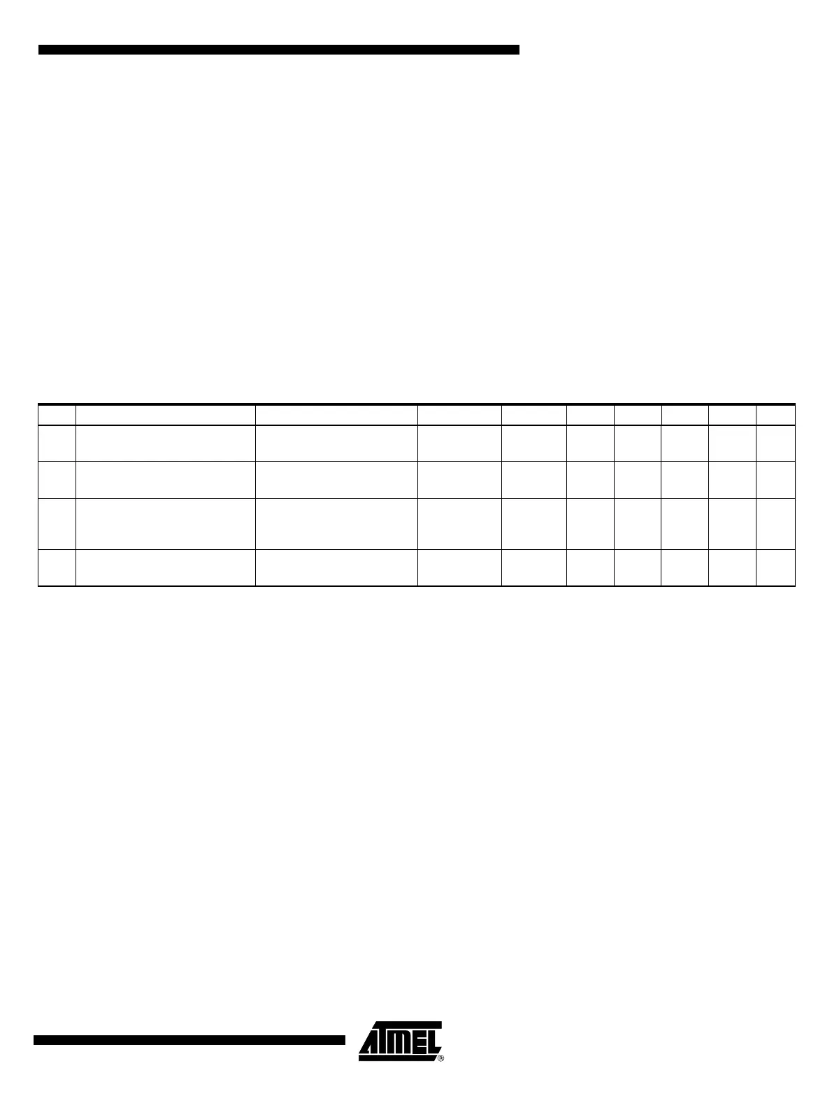
Table 21-1. Electrical Characteristics – Chip Temperature Measurement
No. Parameters Test Conditions Pin Symbol Min Typ. Max. Unit Type*
20.1
Temperature coefficient of
chip-temperature sensor
Chip temperature switched
via AMUX to UZP
UZP V
UZP
–4 –3.6 –3.2 mV/K D
20.2
Output voltage temperature
sensor
Chip temperature switched
via AMUX to UZP, T
J
=25°C
UZP V
UZP
1.29 1.54 V A
20.3
Threshold overtemperature
detection
If overtemperature is
detected, voltage drops by
35 mV
UZP V
UZP
155 185 °C B
20.3a
Hysteresis for overtemperature
detection
UZP V
UZP
525KB
*) Type means: A = 100% tested, B = 100% correlation tested, C = Characterized on samples, D = Design parameter