64
4929B–AUTO–01/07
ATA6264 [Preliminary]
18.15 Ratio V
USP
/V
UZP
For V
VPERI
= 5V (1.5V to 3V)
For V
VPERI
= 5V (> 3V to 25V)
UZP Ratio
6.02 ± 6%
6.02 ± 2.3%
A
A
18.15a Ratio V
USP
/V
UZP
For V
VPERI
= 3.3V (1.5V to 3V)
For V
VPERI
= 3.3V (> 3V to 25V)
UZP Ratio
9.07 ± 6%
9.07 ± 2.3%
A
A
Special Measurement (For Detection of Band-gap Defect)
18.16 Ratio V
VINT
/V
UZP
UZP Ratio 3.99 ± 2.6% A
18.17
Voltage 0.9 × V
VPERI
switched to V
UZP
UZP Ratio (0.9 × V
VPERI
) ± 2% A
18.18
Voltage 0.1 × V
VPERI
switched to V
UZP
UZP Ratio (0.1 × V
VPERI
) ± 2% A
18.19
Input voltage range for
proper function of 10 or 14.6
divider
V
Input
640VA
18.20
Input voltage range for
proper function of 6 or 9.1
divider
V
Input
1.5 25 V A
18.21
Input voltage range for
proper function of 4 and 2
divider
V
Input
46VA
18.22
Input voltage range for
proper function of 1 buffer
V
Input
0.2
V
VPERI
– 0.2
VA
18.23 Ratio V
REF
/V
UZP
–2% 1 0% A
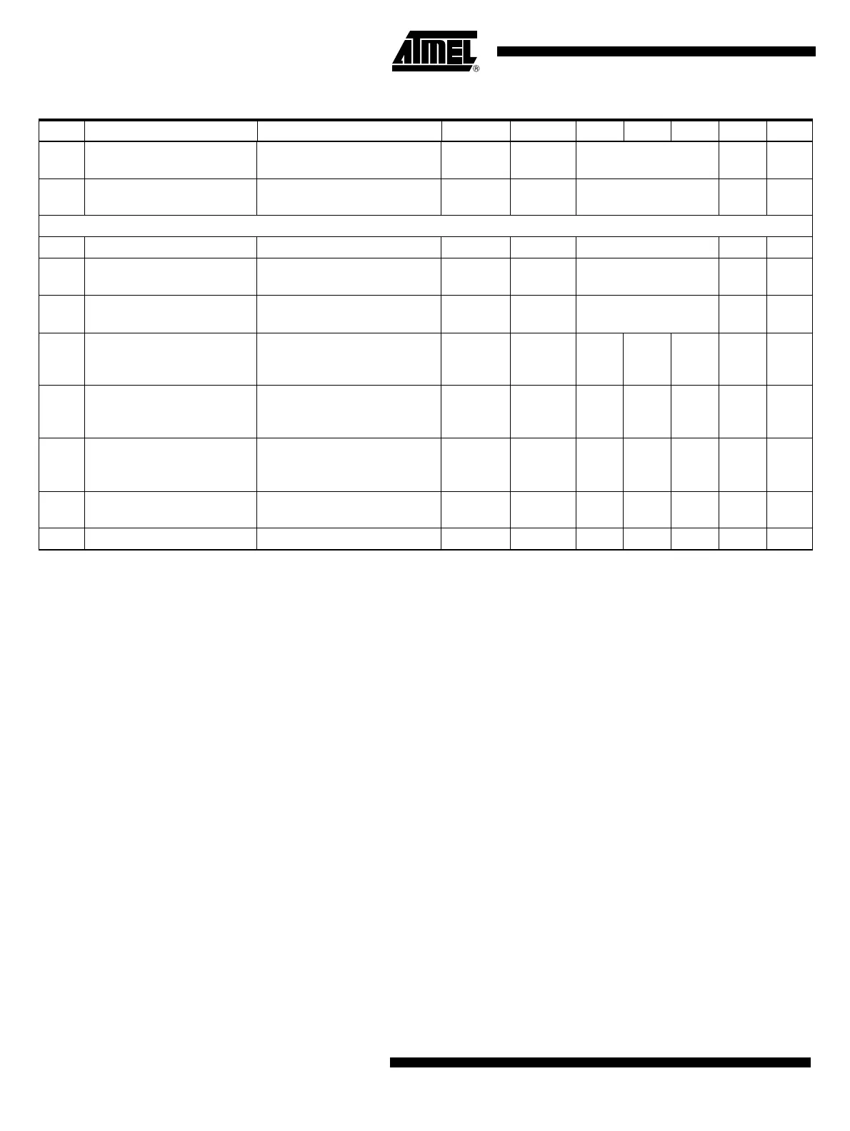
Table 19-1. Electrical Characteristics (Continued)– AMUX (Analog Multiplexer for Voltage Measurements)
No. Parameters Test Conditions Pin Symbol Min Typ. Max. Unit Type*
*) Type means: A = 100% tested, B = 100% correlation tested, C = Characterized on samples, D = Design parameter