72
4929B–AUTO–01/07
ATA6264 [Preliminary]
The initial programming command is only available in Test mode. For more information about
the programming flow and the register contents, see Section 5.2 ”Initial Programming of the
ATA6264” on page 11.
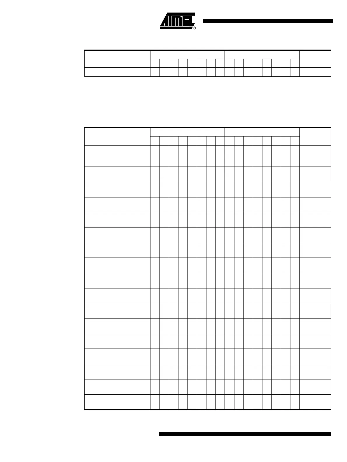
Table 22-6. Initial Programming (IP Command)
Description
MSByte LSByte
Hex Code7654321076543210
Write data to IP register 1 0 1 0 1 0 0 1 x x x x x x x x A9xx
Table 22-7. Diagnosis Commands
Description
MSByte LSByte
Hex Code7654321076543210
Set UZP to tristate mode
and switch off all
measurements
1100000000000000 C000
Switch V
EVZ
via AMUX to
UZP
1100101000110001 CA31
Switch V
VSAT
via AMUX to
UZP
1100101000110010 CA32
Switch 90% × V
VPERI
via
AMUX to UZP
1100101000110100 CA34
Switch 10% × V
VPERI
via
AMUX to UZP
1100101000111000 CA38
Switch V
VCORE
via AMUX to
UZP
1100101001100001 CA61
Switch V
K15
via AMUX to
UZP
1100101001100010 CA62
Switch V
K30
via AMUX to
UZP
1100101001100100 CA64
Switch V
IREF
via AMUX to
UZP
1100101001101000 CA68
Switch V
IASG1
via AMUX to
UZP
1100101010010010 CA92
Switch V
IASG2
via AMUX to
UZP
1100101010010100 CA94
Switch V
IASG3
via AMUX to
UZP
1100101010011000 CA98
Switch V
IASG4
via AMUX to
UZP
1100101011000001 CAC1
Switch V
IASG5
via AMUX to
UZP
1100101011000010 CAC2
Switch V
USP
via AMUX to
UZP
1100101011000100 CAC4
Switch V
K1
via AMUX to
UZP
1100101011001000 CAC8
Switch V
K2
via AMUX to
UZP
1100101011100001 CAE1
Note: 1. UZP voltage will be influenced by the USP voltage