75
4929B–AUTO–01/07
ATA6264 [Preliminary]
The overtemperature bits a5, a6 and a7 are latched when overtemperature is detected. These
bits will be reset with the next SPI command, unless overtemperature still exists.
In the case of a reset, bits b4 and b5 are not set to their default state. These bits show the status
before reset so that the microcontroller can detect whether or not the ATA6264 is in power-up
state.
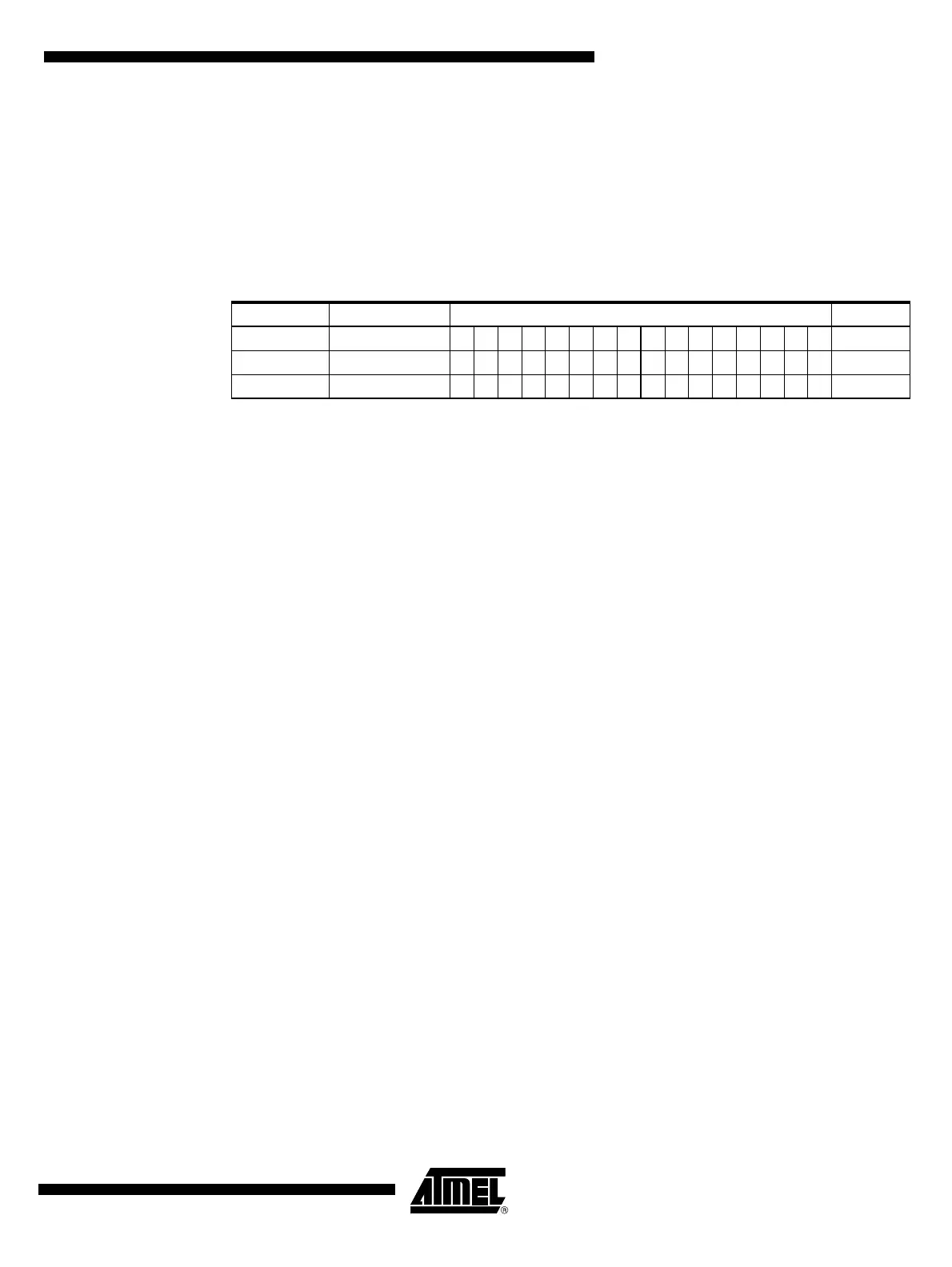
Table 22-12. Test Command Issued via the MISO line as a Result of the Test Mode
Commands
Description Command MISO Answer Hex Code
Test mode 1 55AA 1010101001010101 AA55
Test mode 2 AA55 0101010110101010 55AA
Test mode 3 5500 0 0 0 0 0 0 0 1 a b c d e f g h 01xx
Note: a, b, c, d, e, f, g, h represent the contents of the Initial Programming Register