!
NOTE
This information is for persons with suitable experience should this unit ever require
workshop repair.
16
COMPLETE WORKSHOP MANUAL
!
NOTE
If shaft is difficult to knock out,
remove complete main body
bearing cover housing (see
p.17, Removing Gear Assembly Shaft).
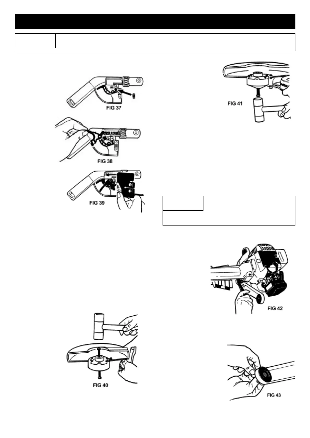
TO REPAIR THROTTLE TRIGGER
ASSEMBLY
1. Remove
2 screws
holding side
cover and
remove cover
and all parts.
Reassemble
as follows.
2. Fit throttle
inter-lock
and
compression
spring
(Fig 37).
3. Fit throttle
trigger with top
hook #43288
and throttle
trigger
compression
spring #43198,
fit trigger then
compression spring (Fig 38).
4. Hold trigger in place with finger until throttle cover
#44069 is fitted (Fig 39). It is then ready for screwing
tight (with 2 screws. Ensure throttle cover rear lug
(arrowed Fig. 39) engages underside of handle wall.
TO REPLACE BLADE SHAFT
1. After removing blades (Refer Pg 10, Figs 25, 26 and
27) remove blade drum #43112, felt seal #42112
and spring level washers #43115. Inspect threaded
end of shaft and file off any rough surfaces so shaft
is round and smooth.
2. Hold unit as
shown in
Fig. 40 and
tap shaft
through using
a 3/8 bolt or
similar so that
bolt replaces
shaft and
maintains
alignment
and contains
washers,
spacer and
gear inside
housing –
DO NOT TURN HOUSING OVER.
3. Carefully push
new blade shaft
#43114 up into
bearing and tap
through carefully
so washers, crown
gear and spacer
remain in position
and the 3/8 bolt is
pushed out
(Fig. 41).
4. When blade shaft comes through, turn assembly
over. Tap blade shaft so head of shaft is against
bearing.
5. Re-assemble in reverse order all parts listed in 1.
above. Refit blade (as per instructions on Pg 10,
Figs 25, 26 and 27) and tighten up to 15-20 ft lbs
(20-27Nm) or hand tight with 8” (200mm) or larger
spanner. Head of blade shaft must pull up tight
against bearing, otherwise blade will become
loose during use.
TO REMOVE ENGINE
1. Remove
throttle cable
(Fig 33B,
page 16),
unclip switch
wire from
motor.
2. Unscrew with
8mm (5/16”)
socket
spanner,
4 screws around
clutch housing Fig 42.
TO REPLACE A.V. MOUNTS
1. Pull worn parts out
and replace with new
(Fig 52) on main
handle moutn.
2. To replace front
A.V. mount rubber –
Remove 2 screws A &
B, split handle
housing, replace
rubber mount and
reverse procedure to assemble Fig 45.