DANGER!
FUEL IS EXTREMELY FLAMMABLE. HANDLE IT
WITH CARE. KEEP AWAY FROM IGNITION
SOURCES. DO NOT SMOKE WHILE FUELING
YOUR EQUIPMENT.
Always allow engine to
cool before refueling.
Accidental spillage of gasoline over a hot engine
could cause fire or explosion to occur. See
Page 4 – Safe Fueling Instructions.
Running the engine with
insufficient oil can cause
serious engine damage. Be sure to check the
engine on a level surface, with the engine
stopped, at regular intervals.
Your Atom Edger is powered by a four-stroke, air cooled
engine which requires unleaded gasoline only in the fuel
tank.
NOTE: Do not mix oil with the gasoline.
Only use sufficient fuel for a few weeks work and store in
an approved safety type container.
Pressure may build up in
the canister. Remove fuel
cap slowly to avoid injury from fuel spray.
Replace fuel cap securely. Take care when
handling gasoline. Avoid direct contact with the
skin and avoid inhaling fuel vapor.
!
WARNING
!
WARNING
!
WARNING
!
WARNING
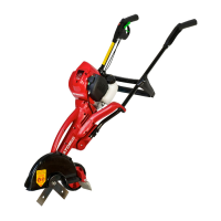
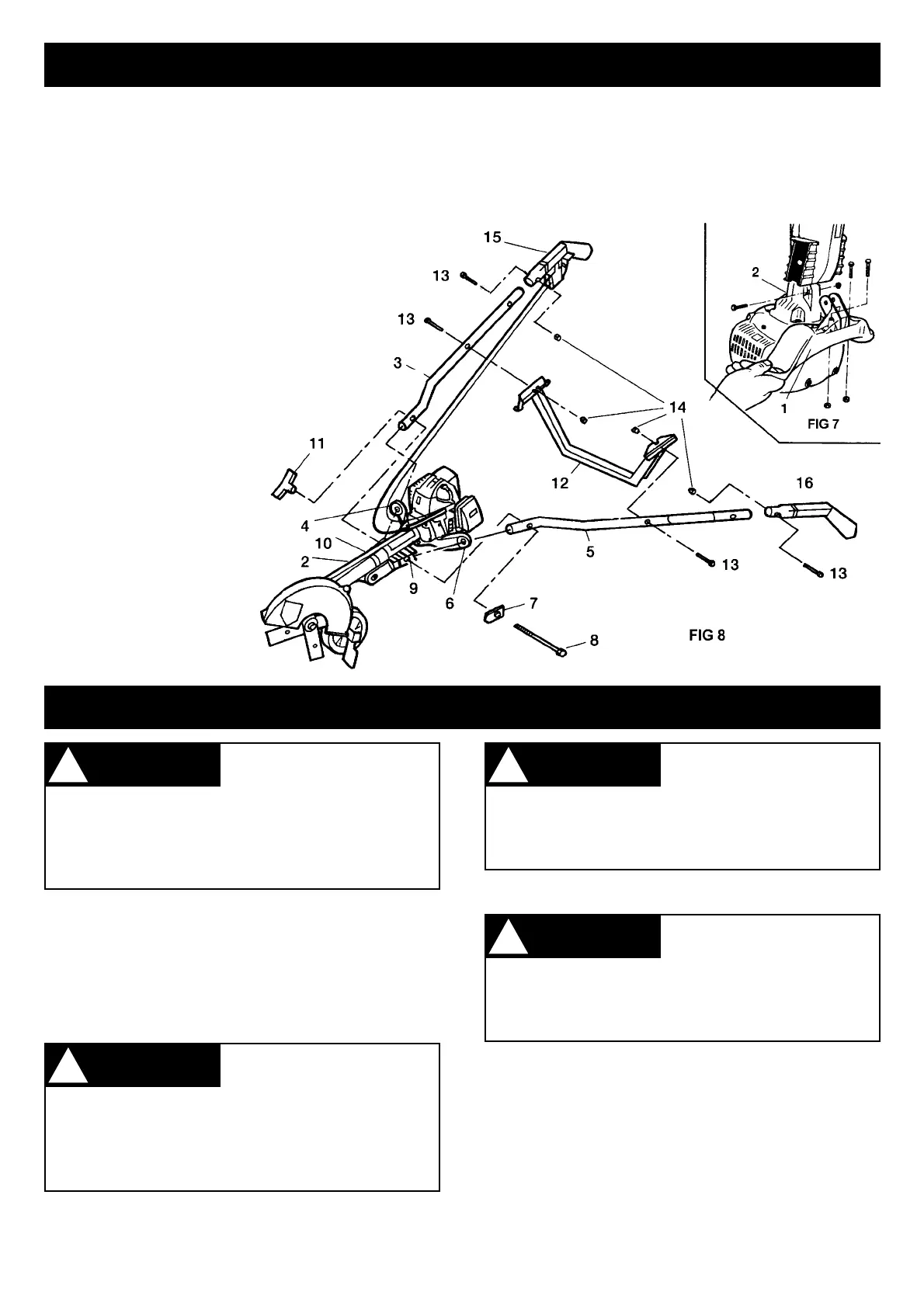
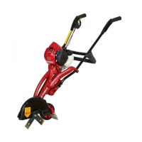
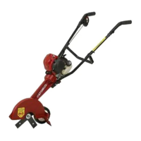
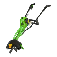
ASSEMBLING THE lll ATOM LAWN EDGER
6
Before fueling the edger, clean the filter cap and the area
around it to ensure that no dirt falls into the tank.
ENGINE OIL LEVEL
1. Remove the oil filler cap and fill tank with oil container
supplied and check the oil level: it should reach the
top of the oil filler neck.
2. If the level is low, fill to the top of the oil filler neck with
the recommended oil.
After every 10 hours use, check the engine oil level and
replenish oil up to the top of the oil filler neck.
FUEL AND OIL
1. Fit A.V. handle brace #1 to main body #2 (Fig. 7)
with screws and nuts provided. Use straight bladed
screwdriver or torx 25 driver.
2. Slide right handle tube #3 through round A.V. rubber
mount #4.
3. Slide left handle tube #5 through round A.V. rubber
mount #6.
4. Point black female hex bolt retainer #7 forward
and insert the 150mm (6”) hex bolt #8 through
retainer, through left handle tube #5, through
left A.V. rubber saddle #9, through main
body #2, through right A.V. rubber
saddle #10, through handle tube #3.
5. Screw on handle wing nut #11
sufficiently. DO NOT
OVERTIGHTEN wing nut as
A.V. becomes less effective.
6. Fit handle cross-brace #12
to handle tubes #3 and
#5. Use 2 screws #13
and 3 lock nuts #14
provided.
7. Insert trigger handle
#15 into right handle
tube #3 using one
screw #13 and one
nut #14 to hold into
place.
NOTE: Throttle cable/switch wire from engine
must be fitted under handle and clipped into
holding lugs of cross-brace #12. Do not loop
throttle/switch wire over handle.
8. Insert left handle #16 into left handle tube #5 using
one screw #13 and one nut #14 to hold in place.