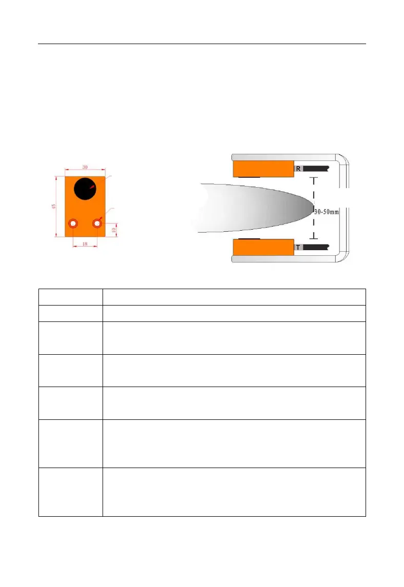
through the valid induction area (at least it should approximately align with the
internal edge of the sensor, or more deeper into the area). The installation position is
recommended as the following diagram.
Note: Net space is required for the sensors' facing area and can't be sheltered by
other metals.
(3) Wiring diagram
DC power input, DC24V±20%; Recommending 24V/500mA
Double-sheet signal output of the Relay (NO position), maximum:
1A/60V
NPN single-sheet/double-sheet signal output, maximum drive:
50mA/48V; PLC or Driving relay can be connected.
PNP single-sheet/double-sheet signal output, maximum drive:
50mA/48V; PLC or Driving relay can be connected.
Transmitting sensors (T), 12 connecting to the red terminal, 13
connecting to the blue terminal, and 14 connecting to the black
terminal.
Receiving ( R ) sensors, 15 connecting to the red terminal,
16connecting to the blue terminal, and 17 connecting to the black
terminal.
 Loading...