TECHNICAL DATA – DUPLEX EASY
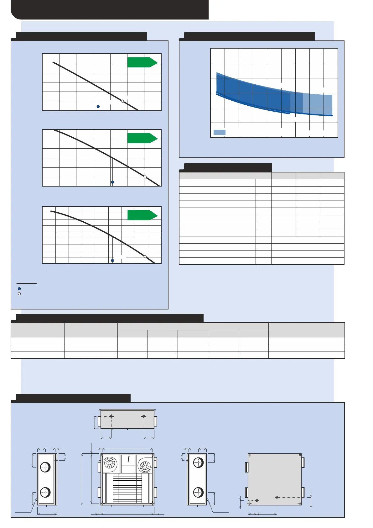
H E A T R E C O V E R Y E F F I C I E N C Y E A S Y
T E C H N I C A L D A T A E A S Y
Max. heat recovery efficiency
Max. power consumption of fans
Diameter of connecting ports
6x 14 (depending on position)
Heat recovery efficiency (%)
100
90
70
95
80
75
85
3
Volume flow rate (m /h)
0
50
Possible condensation region
M = M
i e
150
100 200 250 350300 400 450
250
Easy
300 Easy
400
Easy
P E R F O R M A N C E P A R A M E T E R S E A S Y
Legend:
Pressure reserve with filter G4*
Qref Reference flow rate
Qmax Maximum flow rate
* Max. pressure reserve curve is shown
* Electrical power consumption is shown (both fans and control system)
Pressure reserve p (Pa)
st
3
Volume flow rate (m /h)
D U P L E X 2 5 0 E A S Y
300
0
100
0 150 200
200
10050
400
600
300250 350
500
Pressure reserve p (Pa)
st
D U P L E X 3 0 0 E A S Y
300
0
100
0 150 200
200
10050
400
600
300250 350
500
Pressure reserve p (Pa)
st
D U P L E X 4 0 0 E A S Y
300
0
100
0 150 200
200
10050
500
900
300250 450
700
350 400
600
800
400
D I M E N S I O N A L D I A G R A M E A S Y
850
280
4545
CM
210
100
190
20
80
22,5
22,5B - 45
805
100
190
20
80
135
120
65
165
198
165
K1 K1
K2
K3
K2
K2 K2
K1 K1 K1
K3, K4
K1
K2K2
K3
B
K4
90
D
K3, K4
K4
K1 ... Condensate drain for floor-standing position
K2 ... Condensate drain for underceiling position
K3 ... Condensate drain for floor-standing flat position
K4 ... Condensate drain for floor-standing flat position
* For both floor-standing and underceiling position use only one appropriate
condensate drain.
** For floor-standing flat use both condensate drains.
To achieve acceptable acoustic values it is necessary to install air distribution with guaranteed acoustic attenuation.
* Approximately it is possible to reduce sound power on outlet e , i to following values:
2 2
=
L = 52 dB (A) – using 1 m of soundproofed pipe
w
=
L = 43 dB (A) – using 2 m of soundproofed pipe
w
=
L = 37 dB (A) – using 3 m of soundproofed pipe
w
** Acoustic values of the units with SK cover – see accessories
A C O U S T I C P O W E R L A N D A C O U S T I C P R E S S U R E L
W P
Acoustic power L [dB(A)]
w
Acoustic pressure L [dB(A)]
p
at distance of 3 m
A
A
A
1)
All types of control system that are built in within the unit commonly include at
least two inputs, so the electrical signals from human operation of lights or other
equipment, that automatically control the performance of the unit, can be
connected. These inputs or other types of sensors must always be connected
(e.g. CO , VOC, rH etc.)
2
2)
Maximum flow rate at 100 Pa
3)
The value is at reference flow rate it means 70 % of maximum flow rate
and50Pa
4)
Acoustic values of the units with SK cover – see accessories
48 W
112 W
58 W
126 W
87 W
218 W
 Loading...