DUPLEX EASY
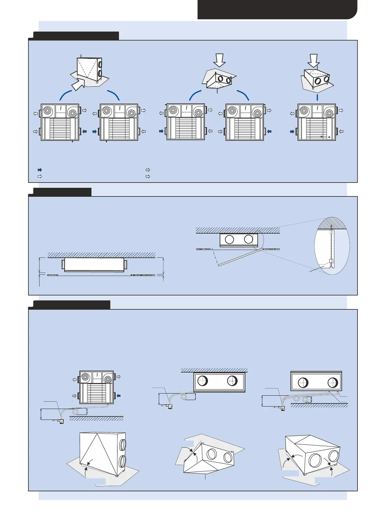
Note: DUPLEX Easy units are supplied for versatile position mounting – the unit can be installed in all positions (floor-standing, underceiling and floor-standing
flat). The ”right hand” and ”left hand” position according to the figure above is selected simply by relocating the operating sensor and by reconnecting unit fans.
M O U N T I N G P O S I T I O N S
F L O OR -S T A N D I N G U N D ER CE I L I N G F L O OR -S T A N D I N G F L AT
L E G E N D
e Fresh outdoor air suction
1
e Fresh filtered air outlet
2
i Exhaust air suction
1
i Exhaust air outlet
2
CM Control module
e
1
e
2
i
2
i
1
RM
i
2
e
1
i
1
RM
e
2
e
1
e
2
i
2
i
1
RM
i
2
e
1
i
1
RM
e
2
i
1
i
2
e
2
e
1
RM
K1 K1
K2
K2
K3K4
I N S T A L L A T I O N
DUPLEX Easy – underceiling position
New DUPLEX Easy units have a very flat design that allows installing
them into even very low suspended ceilings. The minimum
requirements for suspended ceiling void height is 305 mm.
A plasterboard lid is fitted below the unit.
removable door
C O N D E N S A T E D R A I N
Condensate drainage
During heat recovery – heat regaining – moisture is condensated during the cooling of exhaust air. Water condensates on the walls of the
heat recovery exchanger, further increasing heat recovery efficiency. Condensate runs out of the heat recovery exchanger in the direction
of air being extracted and is drained from the DUPLEX unit into a sewer system. For correct functioning and drainage the unit must be
separated from the sewer system using a siphon of asufficient height, the recommended minimum being 150 mm. Small condensation
drain pumps may be used. The unit must be installed within the specified gradient for each position.
e
1
e
2
i
2
i
1
RM
min. 150
min. 150
HL 21
Inlet into
sewer
K1
F L O OR -S T A N D I N G U N D ER CE I L I N G
min 150
min 150
HL 21
Inlet into
sewer
K2
F L O OR -S T A N D I N G F L AT
min. 150
HL 21
Inlet into
sewer
min. 150
K3
K4
i
2
i
1
i
2
3° = 25 mm
10° = 75 mm
12° = 100 mm
3° = 25 mm
 Loading...