9
ACCUMULATION TANKS
EN
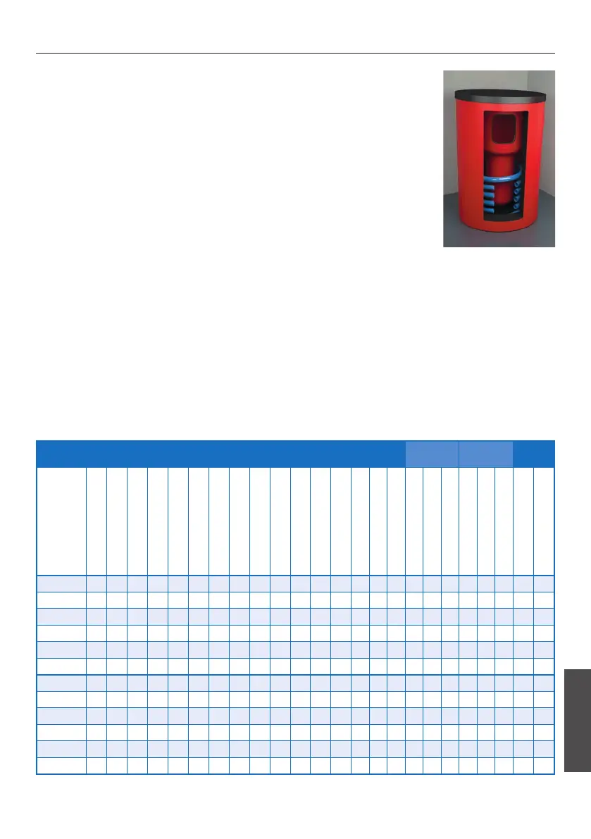
DESCRIPTION
The accumulation tanks ATTACK HR, HRS are made from the quality steel
and serve for accumulation of the heating water as well as for preparation of
the D.H.W. by an internal enameled exchanger. The ATTACK HRS model is
accessorized with an extra exchanger to be connected to the solar system.
Tanks of this type have abuilt-in magnesium anode in the D.H.W. tank to
increase resistance against corrosion. The manual deaeration valve is instal-
led in the upper part.
ATTACK HR: 9× socket G1 ½", 6× socket G½"
ATTACK HRS: 9× socket G1 ½", 6× socket G½", 2× socket G1" – solar circuit
KEY FOR THE ACCUMULATION TANKS
1 – Flow connection – boiler . . . . . . . . . . . . . 1 ½"
2 – Freely disposable . . . . . . . . . . . . . . . . . . 1 ½"
3 – Electrical heating coil (EL) . . . . . . . . . . . . 1 ½"
4 – Freely disposable . . . . . . . . . . . . . . . . . . 1 ½"
5 – Return connection – heating circuit . . . . . . 1 ½"
6 – Flow connection – heating circuit (radiators) 1 ½"
7 – Flow connection – heating circuit (oor) . . . 1 ½"
8 – Return connection – gas, oil and pellet boiler 1 ½"
9 – Return connection – wood boiler . . . . . . . 1 ½"
10 – Sensor of solar system or heating . . . . . . . ½"
AS – Flow connection of solar system . . . . . . . . 1"
RS – Return connection of solar system . . . . . . . 1"
D1 – Diameter without insulation
D2 – Diameter with insulation
CN – Pump of the circulation tank . . . . . . . . . . ¾"
AF – Cold drinking water . . . . . . . . . . . . . . . . ¾"
AC – Hot drinking water . . . . . . . . . . . . . . . . . ¾"
MA – Magnesium anode . . . . . . . . . . . . . . . . . –
TECHNICAL PARAMETERS
Tank
Solar
exchanger
Internal
tank
Tank
Type
Position 1–6
Position 2–7
Position 3
L-max. length of the el. heating
body
Position 4–8
Position 5–9
Position RS
Position AS
∅ D1 – Diameter without
insulation
∅ D2 – Diameter with
insulation of 100 mm
Height
Height with insulation of
100 mm
R – Slope dimension without
insulation
Max. operating temperature (°C)
Static loss (W)
Max. operating pressure (bar)
Area of exchanger (m²)
Volume of exchanger (l)
Max. operating pressure (bar)
Volume (l)
Max. operating temperature (°C)
Max. operating pressure (bar)
Volume (l)
Weight (kg)
HR600K
1515 1123 794 650 684 245 - - 700 900 1754 1854 1841 95 99 3 - - - 170 95 6 435 161
HR800K
1545 1135 846 735 725 315 - - 790 990 1806 1906 1898 95 105 3 - - - 170 95 6 543 176
HR1000K
1735 1255 1036 735 775 295 - - 790 990 1996 2096 2081 95 121 3 - - - 170 95 6 721 185
HR1250K
1655 1175 988 880 695 285 - - 950 1150 1948 2048 2064 95 142 3 - - - 170 95 6 1069 225
HR1500K
1755 1345 1072 920 820 375 - - 1000 1200 2032 2132 2160 95 161 3 - - - 170 95 6 1250 265
HR2000K
1955 1408 1314 1000 862 315 - - 1100 1300 2274 2374 2390 95 188 3 - - - 170 95 6 1790 361
HRS600K
1515 1123 794 650 684 245 245 725 700 900 1754 1854 1841 95 99 3 1,8 11,9 10 170 95 6 435 199
HRS800K
1545 1135 846 735 725 315 315 725 790 990 1806 1906 1898 95 105 3 2,4 15,9 10 170 95 6 543 218
HRS1000K
1735 1255 1036 735 775 295 295 860 790 990 1996 2096 2081 95 121 3 3 19,8 10 170 95 6 721 241
HRS1250K
1655 1175 988 880 695 285 285 850 950 1150 1948 2048 2064 95 142 3 3 19,8 10 170 95 6 1069 280
HRS1500K
1755 1345 1072 920 820 375 375 895 1000 1200 2032 2132 2160 95 161 3 3,6 19,8 10 170 95 6 1250 328
HRS2000K
1955 1408 1314 1000 862 315 315 843 1100 1300 2274 2374 2390 95 188 3 4,2 23,7 10 170 95 6 1790 361
 Loading...