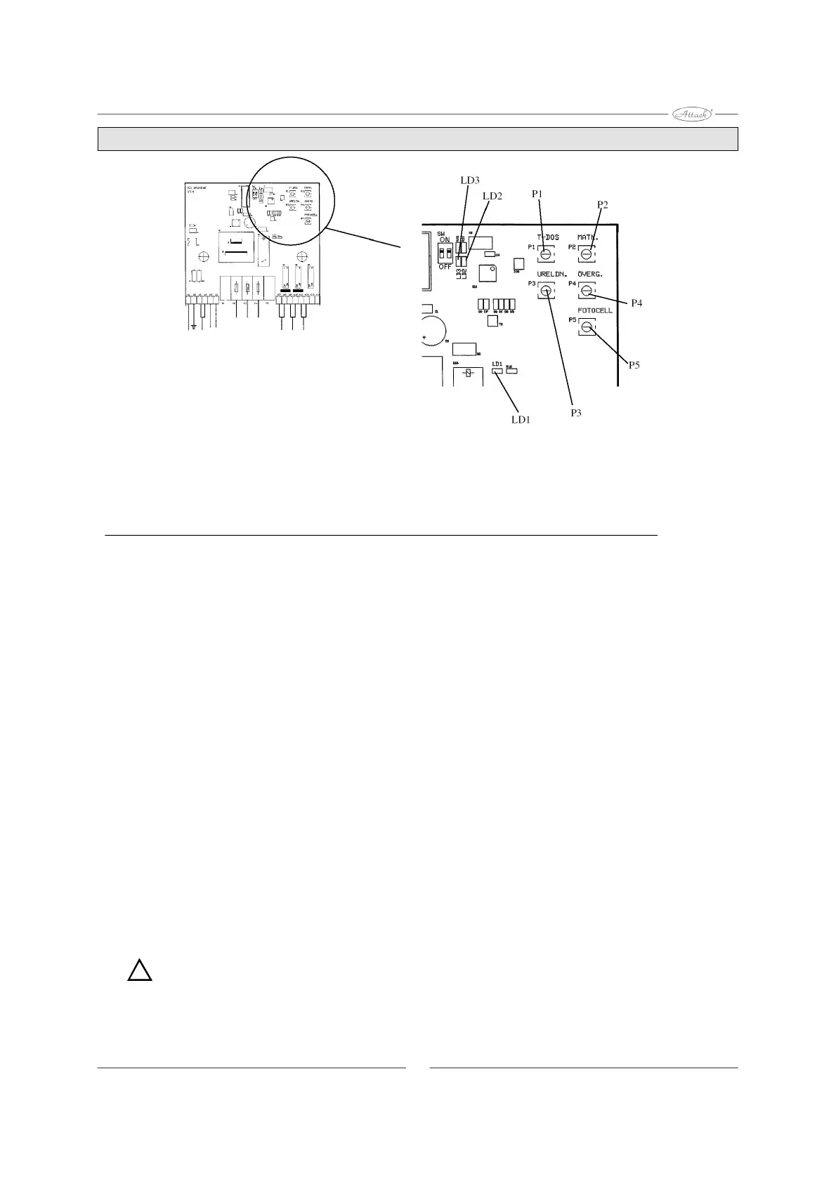
The settings of control electronics
Functions P1- P5
Reading the values on potentiometer
CAUTIONDo not change any values during the operation time - high voltage
on the control panel !
Potentiometers P1- P5 are potentiometers for fine settings of burner functions.
The control panel has three light diodes (LD1,LD2,LD3).
P- 1 Interval of feeding 30 - 165 sec. Pellets should lightly cover upper
ignition openings of the grate;
approximatelly 0,2-0,25 l.
P- 2 Feeding cycle 1,5 - 8,21 sec. Time of pellet feeding every 15 sec.
P- 3 Burning out time 30 - 300 sec. Fan running time, when the photocell
does not detect the flame.
P- 4 Transitional interval 45 - 450 sec. Time between ignition and normal
(starts with 25% feeding) operation.
P- 5 Photocell sensitivity 0 - 9 9 = max. sensitivity on light/flame
0 = min. sensitivity on light/flame
For reading the value set on given potentiometer firstly the green diode LD3 is blinking for
given potentiometer and follow on yellow diode LD2 blinking for the value set on this
potentiometer. This is done continuously - Pot. 1, 2, 3, 4, 5, 1, 2, .... - no matter if the burner is in
operational or stand-by mode.
For example: 3 x green blink is followed by 6 x yellow blink - it means that P-3 is set to burning
out time of 210 seconds, after the photocell has detected the flame. (see Tabel of settings).
:
Pot. Function Range of settings Description/Note
!
7
 Loading...