EasyManuals Logo

Auber Instruments Auberins KIT-GGP User Manual

Auber Instruments Auberins KIT-GGP
30 pages
To Next Page IconTo Next Page
To Previous Page IconTo Previous Page
Page #2 background imageLoading...
Page #2 background image
- 2 -
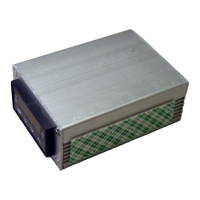
Fig 2. Solid state relay (SSR), mounting screw, silicone heat transfer compound (white
paste in the plastic vial) for SSR, and spiral-cut tubing for protecting exposed cable.
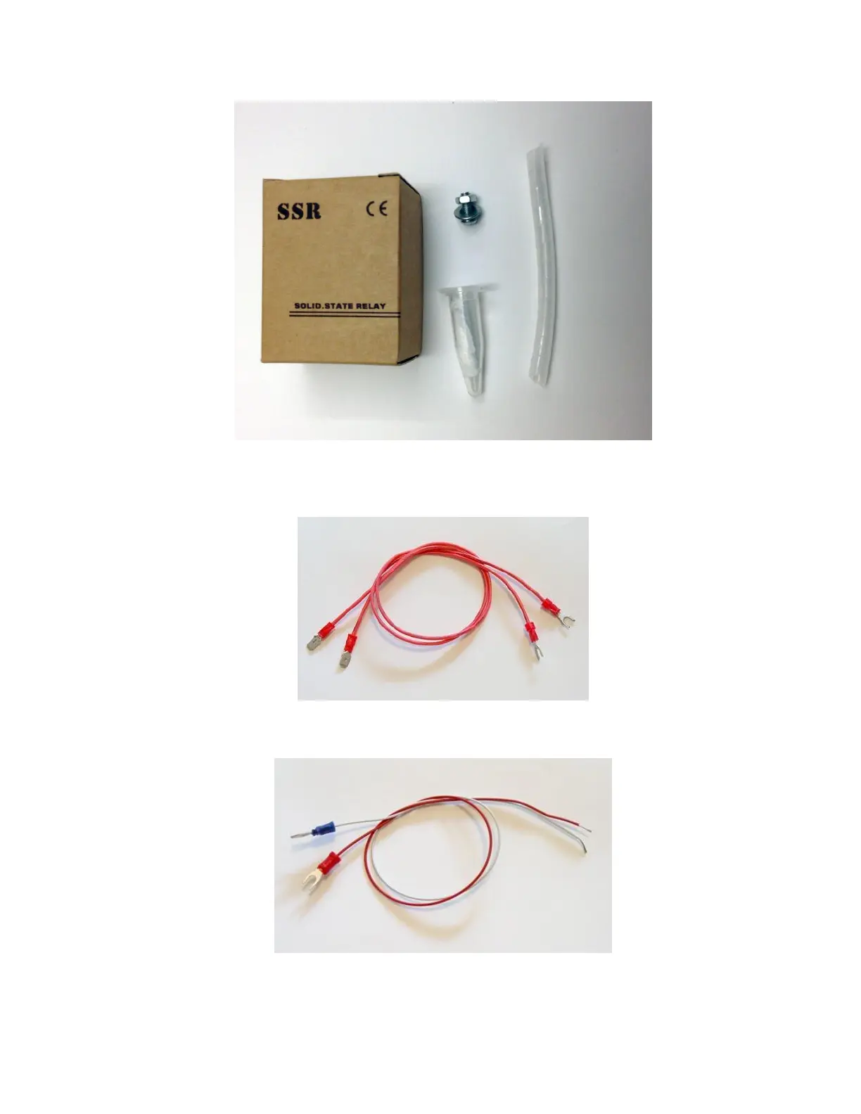
Fig 3. Cables for connecting SSR output to heater. Terminated with spade tongue
terminal on one end and tab terminal on the other end.
Fig 4. Cables for connecting controller output to SSR input. Red-colored cable for
positive. White-colored cable for negative. One end is terminated with spade tongue
terminal.

Questions and Answers:

Question and Answer IconNeed help?

Do you have a question about the Auber Instruments Auberins KIT-GGP and is the answer not in the manual?

Auber Instruments Auberins KIT-GGP Specifications

General IconGeneral
BrandAuber Instruments
ModelAuberins KIT-GGP
CategoryController
LanguageEnglish

Related product manuals