Do you have a question about the Auber Instruments KIT-RSPb and is the answer not in the manual?
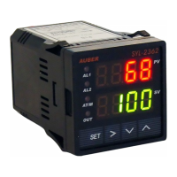
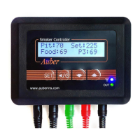
Identifies the PID controller and associated components shown in the front and back views.
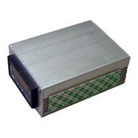
Describes the dual solid state relay (SSR) included in the kit, noting its dual functionality for steam and brew control.
Details the red cables used for connecting the SSR output to the brew thermostat wiring.
Details the black cables used for connecting the SSR output to the steam thermostat wiring.
Describes cables connecting the controller's brew control output to the SSR brew control input.
Explains cables for connecting the controller's steam control output to the SSR steam control input.
Identifies cables used for tapping power to the controller, noting their colors and connectors.
Shows and identifies the RTD temperature sensor used for temperature measurement.
Identifies cable ties, a common accessory for organizing wires.
Shows the green cable specifically for controlling the brew pump.
Details heat transfer compound, RTD jumper cable, and brew pump control jumper cable.
Identifies the green ground wire for the controller box.
Outlines initial steps before installation, including disconnecting power and removing components.
Details the process of mounting the Solid State Relay (SSR) onto the machine's base.
Explains how to connect the SSR cables and the grounding wire to the machine.
Guides the installation of components within the top compartment of the espresso machine.
Covers the final wiring and connection steps for the main controller unit.
Provides the original wiring diagram for the Rancilio Silvia espresso machine.
Shows the modified wiring diagram incorporating the KIT-RSPa controller.
| Output | Relay |
|---|---|
| Maximum Current | 10A |
| Display Type | LED |
| Input | Thermocouple |
| Power Supply | 110-240V AC |
| Dimensions | 48mm x 48mm x 110mm (1.89" x 1.89" x 4.33") |
| Controller Type | PID Controller |