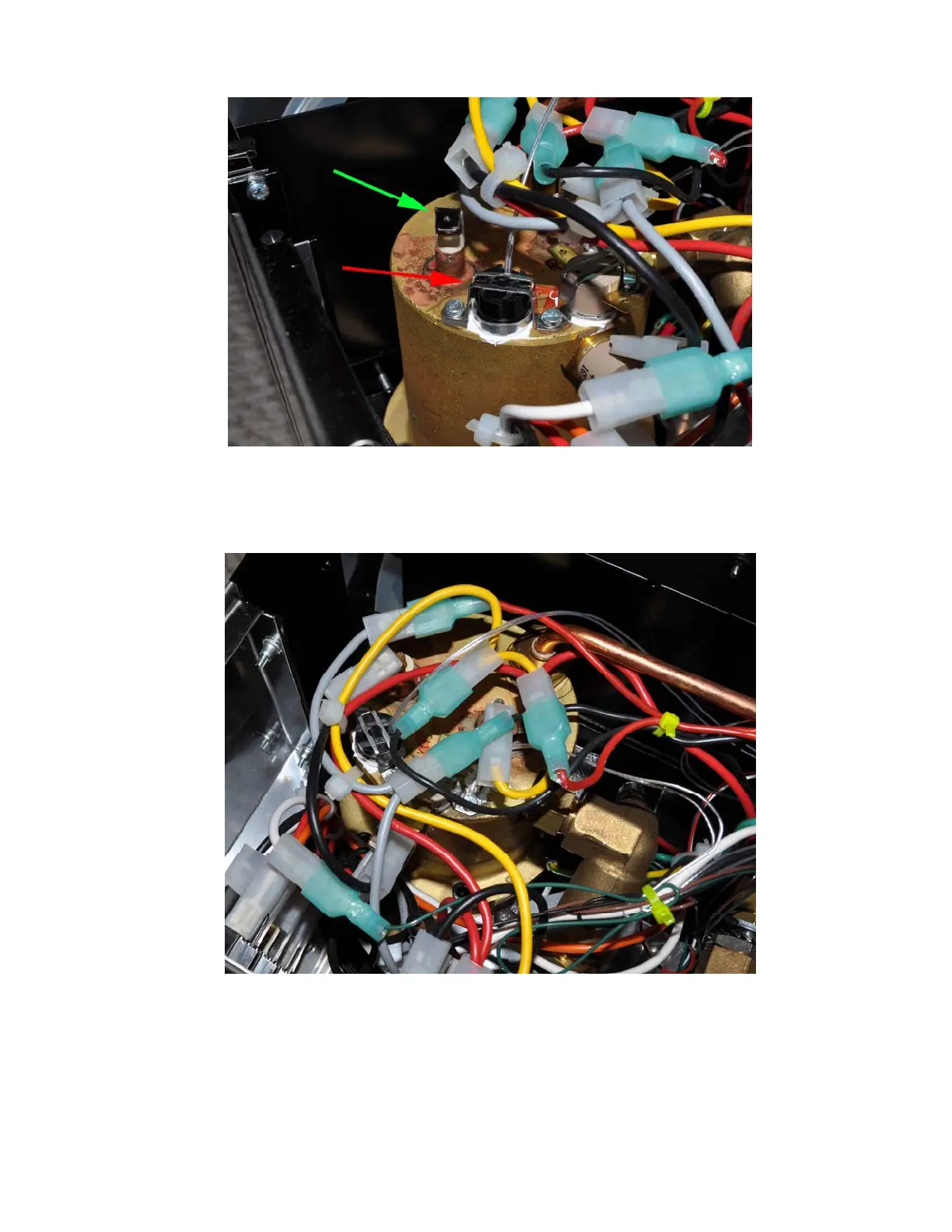
Figure 22a. Red arrow shows the RTD sensor installed in the bracket that was for the brew
thermostat. The cable to the heater has been removed for easy installation (green arrow).
When installing the cable back, be sure to push the connector all the way in. Failure to
installed the cable back to its original position might result in cable overheat and damage.
Figure 22b. RTD sensor installed
2) The power for the controller box is tapped from the main power switch by using the
piggyback connectors on the black and brown cables. Remove the connectors with black and
red cables on the main power switch (red arrows in Figure 23a). Remember the original
position: the connector with black cable was on the left and connector with red cable in the
center. Slide the two controller power cable piggyback connectors on to the switch as shown
14