in Figure 23b. The tab on the piggyback connector should be on the top. You need to bend it
downward a little bit if the angle is too high. It is very important that black cable is put on the
left side of the switch and brown cable on right. After installing the connectors, connect the
cables that were just removed to the tab on the piggyback connector. It is very important to
keep the original position, black on the left and red in the center (see Figure 23c)
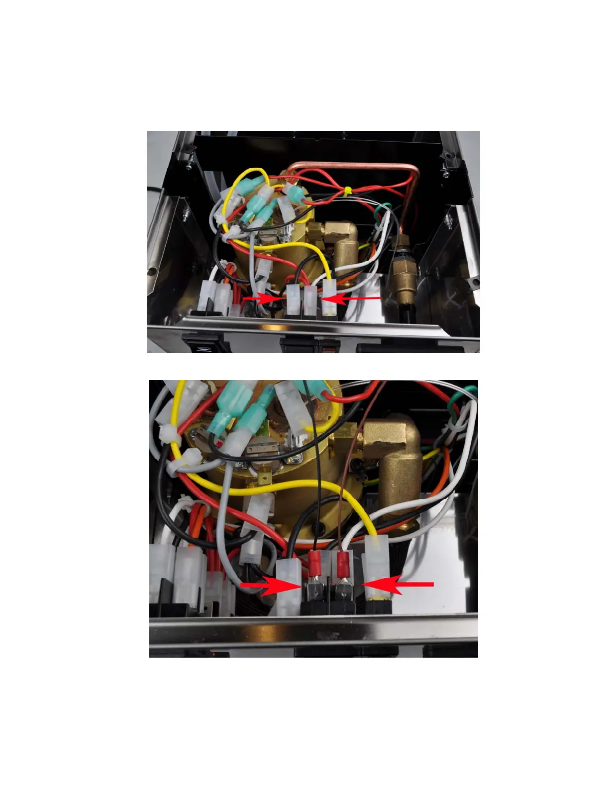
Figure 23a. Red arrow indicates the connectors that controller power cable will be tapped.
Figure 23b. The controller power cable piggyback connector location. (red arrows).
Brown cable on the right and black cable on the left.
15