AUBER INSTRUMENTS WWW.AUBERINS.COM
2024.01 P1/7
SYL-3615 Wi-Fi BBQ Controller
Firmware v1.1.86
Document version 1.0 (Jan, 2024)
Caution
This controller is designed for use under normal operating conditions within
the temperature range of 32°F to 122°F (0°C to 50°C) with a Relative
Humidity of less than 85%. Please refrain from exposing the controller to
water or rain, and avoid placing it under direct sunlight on hot days. When
not in use, store the controller in a cool and dry environment.
This controller comes with a one-year warranty, limited to the controller only.
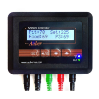
1. Front Panel and Connection Ports
6. Wi-Fi indicator
7. Output indicator
8. Pit probe
9. Food probe
10. Probe 3
1. LCD display
2.SET key
3.TIMER/BACK key
4.D own key
5.Up key
12.Power adapter
connector
11.Fan connec tor
Figure 1. Front panel of a SYL-3615 controller.
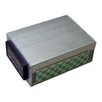
17. Power-in socke t
16. Output sock et (fan)
15. P3 port (probe 3)
14. P2 port (food)
13. P1 port (pit)
Figure 2. Connection ports on the bottom of a SYL-3615.
Table 1. Recognizing Different Parts on a SYL-3615.
#
Name Description
1 LCD Display Show probe readings and other information.
2 SET Key * Short-press to access the cooking profile.
* Long-press to access menus.
3 TIMER / BACK
Key
* Check status (step number, time, and output).
* Cancel the Open-Lid function.
4 DOWN Key * Mute the buzzer.
* Scroll down in the menu.
* Decrease the value.
5 UP Key * Scroll up in the menu.
* Increase the value.
6 Wi-Fi Indicator * Solid: connected to Wi-Fi and the server.
* Slow-blinking: lost connection.
* Fast-blinking: ready to pair (AP mode).
7 Output Indicator Display the output status to the fan.
8 Pit Probe The probe that measures the pit temperature.
9 Food Probe A pointed probe can be inserted into food.
10 Probe 3 A third probe for monitoring food temperature.
11 Fan Connector DC connector from the fan, 2.5 mm x 5.5 mm.
12 Power Adapter
Connector
DC connector, 2.1 mm x 5.5 mm. Supplies 12
VDC from the power adapter.
13 P1 Sensor port for the pit probe.
14 P2 Sensor port for the food probe.
15 P3 Sensor port for the third probe.
16 Output to Fan Output port for the fan, 2.5 mm x 5.5 mm.
17 Power-In Power input socket, 2.1 mm x 5.5 mm.
2. Getting Started
2.1 Powering Up the Device
Simply connect the 12 VDC power adapter to a wall outlet and then plug
the barrel connector (2.1 mm x 5.5 mm) to the power-in socket located
on the very left port at the bottom of the SYL-3615 controller (refer to
Figure 2).
The controller’s LCD screen should illuminate and display its model
number and the firmware version (Figure 3a) for a few seconds.
Subsequently, the LCD screen will change to the normal display mode
(Figure 3b). The “-H-” is a sensor error code, which means no probe is
connected or detected.
SYL-3615
v1. 1. 86
Figure 3(a). The display screen when controller is just powered up.