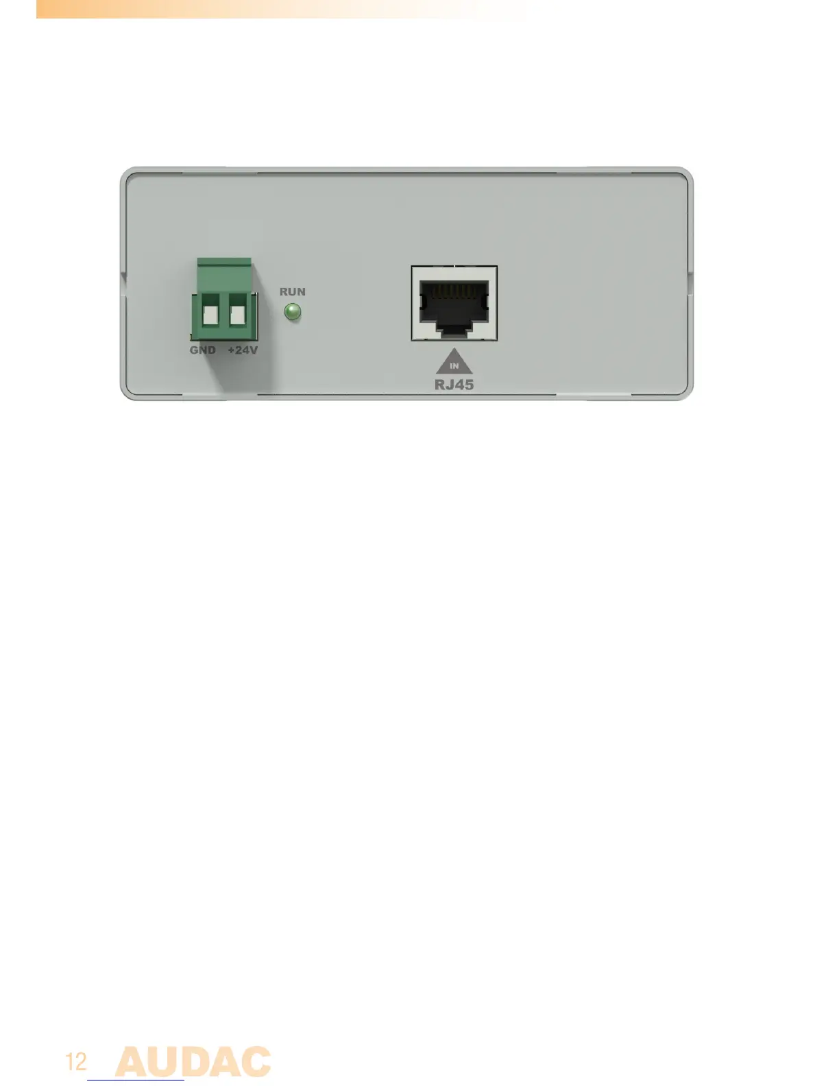
Rear panel
The rear panel of the APG20
MK2
contains the 24 Volts DC input connection, together with
the RJ45 bus input connection whereto the twisted pair bus cabling has to be connected.
1) 24 Volts power connector:
The 24 Volts power supply connection is implemented using a terminal block
connection on the left side APG20MK2‘s rear panel. The included power supply
(PSD241) should be connected here. This input is accompanied with a green ‘RUN’
indicator LED which will illuminate when the device is operational.
Mind the polarity when connecting the power supply.
2) RJ45 Bus input connection:
The RJ45 connection connects the remote input and control modules to the
APG20MK2. This connection carries two analogue audio pairs, an RS485 data pair
and 24 Volts distribution to the transmitter end. More information over the connection
possibilities can be found in the next chapter of this instruction manual.