Chapter 1
Connections and connectors
CONNECTION STANDARDS
The in- and output connections for AUDAC audio equipment are performed
corresponding to international wiring standards for professional audio equipment.
Cinch (RCA):
For unbalanced line output connections
Tip: Signal Sleeve: Ground
White: Left Red: Right
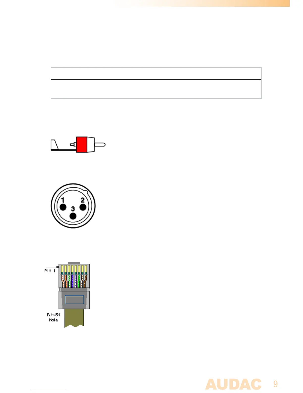
XLR:
For balanced line / microphone output connections
Pin 1: Ground
Pin 2: Signal +
Pin 3: Signal -
RJ45 Bus input (RS485, Audio, +24 V DC):
For connection to audio input & control units
Pin 1 White-Orange AUDIO WLI +
Pin 2