20
System components
p
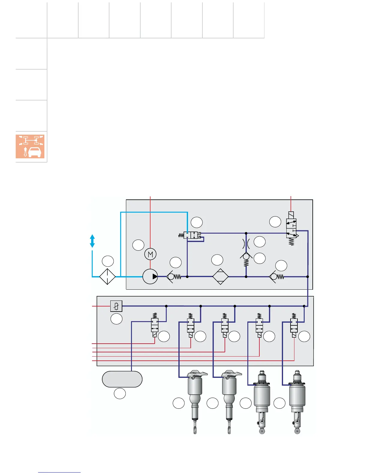
Pneumatic diagram
1 Additional noise damper
2 Non-return valve 1
3 Air dryer
4 Non-return valve 3
5 Non-return valve 2
6 Discharge throttle
7 Pneumatic discharge valve
8 Compressor V66
9 Electric discharge valve N111
10 Pressure sensor G291
243_030
1
2
3
4
6
5
7
9
10
11 12 13 14 15
16
17 18 19 20
11 Valve for pressure accumulator N311
12 Valve for FL suspension strut N148
13 Valve for FR suspension strut N149
14 Valve for RL suspension strut N150
15 Valve for RR suspension strut N151
16 Pressure accumulator
17 Front left air spring
18 Front right air spring
19 Rear left air spring
20 Rear right air spring
from the compressor
relay
from control unit
to the
control unit
from the
control unit
8