Page 3 - 10
R-60 / Nov 1994R-60 / Nov 1994
R-60 / Nov 1994R-60 / Nov 1994
R-60 / Nov 1994
CC
CC
C
ONSOLEONSOLE
ONSOLEONSOLE
ONSOLE
L L
L L
L
OGICOGIC
OGICOGIC
OGIC
& I/O C & I/O C
& I/O C & I/O C
& I/O C
ONNECTIONSONNECTIONS
ONNECTIONSONNECTIONS
ONNECTIONS
MODULE I/O CONNECTIONS
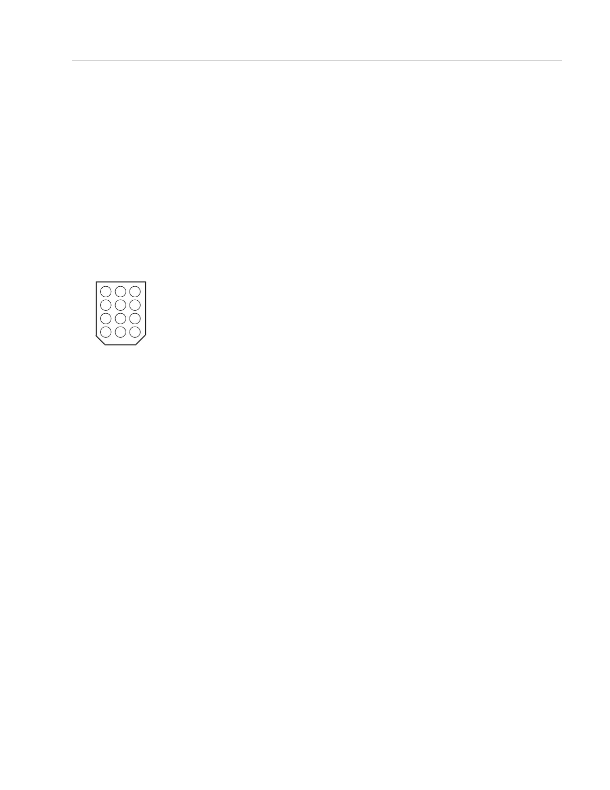
Module input/output signal connections are made via 12–pin AMP type
connectors. Refer to the R-60 Mother board load sheet on page 7-2 for the
exact location of specific connectors. Key drawing to left shows a typical
connector. Note this key drawing applies to all 12–pin I/O connector text
pinouts that follow in this section.
Note also that the audio signal connections follow a logical pattern. Pins
are grouped in 4 groups (called pairs for this discussion) of 3 pins each (1-3,
4-6, 7-9, and 10-12). The first pin of each group (1, 4, 7, and 10) is audio
common, or ground, for connection of shields. The next pin (2, 5, 8, and 11)
is the low side for balanced signals, or ground for unbalanced signals. The
third pin (3, 6, 9, and 12) is the high side for balanced signals, or the signal
connection for unbalanced ones.
In the case of stereo signals, left is always assigned to the first (pins 1-3) or
third (pins 7-9) pair of a connector, and right is always assigned to the second
(pins 4-6) or fourth (pins 10-12) pair.
The PROGRAM, AUDITION, MONO, CONTROL ROOM and STUDIO outputs
are electronically balanced, 10 ohms output impedance; minimum load is 600
ohms.
As the outputs are electronically balanced, care must beAs the outputs are electronically balanced, care must be
As the outputs are electronically balanced, care must beAs the outputs are electronically balanced, care must be
As the outputs are electronically balanced, care must be
exercised when connecting them to an unbalanced system. exercised when connecting them to an unbalanced system.
exercised when connecting them to an unbalanced system. exercised when connecting them to an unbalanced system.
exercised when connecting them to an unbalanced system. While
temporarily shorting the low side of the output signal to ground will not cause
any problems, continued operation will result in increased distortion, de-
creased reliability, and possible oscillation problems.
If you must connectIf you must connect
If you must connectIf you must connect
If you must connect
the output to an unbalanced system, be sure to leave the low sidethe output to an unbalanced system, be sure to leave the low side
the output to an unbalanced system, be sure to leave the low sidethe output to an unbalanced system, be sure to leave the low side
the output to an unbalanced system, be sure to leave the low side
unterminated, and connect the unbalanced system to the high sideunterminated, and connect the unbalanced system to the high side
unterminated, and connect the unbalanced system to the high sideunterminated, and connect the unbalanced system to the high side
unterminated, and connect the unbalanced system to the high side
output and shield connections.output and shield connections.
output and shield connections.output and shield connections.
output and shield connections.
IN-60 Audio InputIN-60 Audio Input
IN-60 Audio InputIN-60 Audio Input
IN-60 Audio Input
(CT1-CT14, R-60 Mother Board load sheet dwg)
(CT1-CT6, R-60 Ext Mother Board load sheet dwg)
Pin 1 - A INPUT LEFT, SHIELD
Pin 2 - A INPUT LEFT, LOW
Pin 3 - A INPUT LEFT, HIGH
Pin 4 - A INPUT RIGHT, SHIELD
Pin 5 - A INPUT RIGHT, LOW
Pin 6 - A INPUT RIGHT, HIGH
Pin 7 - B INPUT LEFT, SHIELD
Pin 8 - B INPUT LEFT, LOW
Pin 9 - B INPUT LEFT, HIGH
Pin 10 - B INPUT RIGHT, SHIELD
Pin 11 - B INPUT RIGHT, LOW
Pin 12 - B INPUT RIGHT, HIGH
Key diagram showing back of
typical 12-pin I/O connector
plug, with pin numbers oriented
as they would be seen while
wiring. Beveled corners
correspond to PCB mounted
mating sockets.
5 46
8 79
11 1012
2 13
R-60 / July 1997
Page 3 - 9
 Loading...