LR 211 XR
11
DEUTSCH
TECHNISCHE DATEN
NETZTEIL 11 ÷ 15 VDC
RUHESTROM 1 A
MAXIMALER STROMVERBRAUCH (bei Nennleistung) 20 A
MAX DYNAMIC POWER (1 Kanäle je 4 Ohm Last) 210 W
MAX DYNAMIC POWER (1 Kanäle je 2 Ohm Last) 420 W
NENNLEISTUNG (Tol. +10 %; -5 %)
1 Kanäle je 4 Ohm Last; 0,3 % Klirrfaktor; 12 VDC 140 W (RMS)
DAUER-AUSGANGSLEIST. (1 Kanäle je 4 Ohm Last; 13,8 VDC) 155 W (RMS)
DAUER-AUSGANGSLEIST. (1 Kanäle je 2 Ohm Last; 13,8 VDC) 250 W (RMS)
IMPULSIVE OUT POWER (1 Kanäle je 1 Ohm Last; 13,8 VDC) 410 W (RMS)
KLIRRFAKTOR THD (bei 1 KHz; 90 % Nennleistung) 0,07 %
DÄMPFUNGSFAKTOR (4 Ohm) 120
ANSTIEGSZEIT 4,5 µS
STORABSTAND 98 dBA
EINGANGSEMPFINDLICHKEIT 0,3 V ÷ 4 VRMS
EINGANGSIMPEDANZ 15 KOhm
LASTIMPEDANZ 8 - 4 - 2 Ohm
CROSSOVER FREQUENZ 50; 60; 80; 100; 120 Hz
FLANKENSTEILHEIT
12 dB/Oct. Butterworth
LO-BOOST FREQUENZ 45 Hz
LO-BOOST GEWINN 0 / +6 dB
HI-PASS AUSGANGSGEWINN 0 dB
REMOTE IN 7 ÷ 15 VDC
ABMESSUNGEN (BxHxT) 175 x 50 x 330 mm
FRANÇAIS
DONNÉES TECHNIQUES
ALIMENTATION 11 ÷ 15 VDC
CONSOMMATION MIN. 1 A
CONSOMMATION MAX. (Puissance Nominale) 20 A
MAX DYNAMIC POWER (1 Ch x 4 Ohm) 210 W
MAX DYNAMIC POWER (1 Ch x 2 Ohm) 420 W
PUISSANCE NOMINALE CONTINUE (Toll. +10 %; -5 %)
1 ch x 4 Ohm; 0,3 % DHT; 12 VDC 140 W (RMS)
PUISSANCE SORTIE CONT. (1 ch x 4 Ohm; 13,8 VDC) 155 W (RMS)
PUISSANCE SORTIE CONT. (1 ch x 2 Ohm; 13,8 VDC) 250 W (RMS)
IMPULSIVE OUT POWER (1 ch x 1 Ohm; 13,8 VDC) 410 W (RMS)
DISTORSION HARM. TOTALE (1 KHz; 90 % Puiss. Nom.) 0,07 %
COEFFICIENT D'AMORTISSEMENT (4 Ohm) 120
TEMPS DE MONTEE 4,5 µS
RAPPORT SIGNAL/BRUIT 98 dBA
SENSIBILITE D'ENTREE 0,3 V ÷ 4 VRMS
IMPEDANCE D'ENTREE 15 KOhm
IMPEDANCE DE CHARGE 8 - 4 - 2 Ohm
FREQUENCES DE COUPURE 50; 60; 80; 100; 120 Hz
PENTE DES FILTRES 12 dB/Oct. Butterworth
FRÉQUENCE DU FILTRE LO-BOOST 45 Hz
GAIGNE DU FILTRE LO-BOOST 0 / +6 dB
GAIGNE SORTIES HI-PASS 0 dB
REMOTE IN 7 ÷ 15 VDC
DIMENSIONS (BxHxL) 175 x 50 x 330 mm
14
LR 131 XR - LR 211 XR
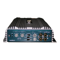
CONTROLS AND FUNCTIONS
FREQUENCY
SWITCH
INDICATORS
LIGHTS
X-OVER
Crossover sec-
tion.
Tripping
adjustment for
selecting HI-
PASS / LO-
PASS
crossover
frequency.
Filters slope is
12 dB/Oct.
(crossover at -3
dB).
Frequencies
can be chosen
among: 50-60-
80-100-120 Hz.
HI-PASS
frequencies can
be obtained in
stereo from
OUT-HI out-
puts, while LO-
PASS
frequencies are
mixed in mono
and amplified
on the output
connectors
(SPEAKERS).
ON
Lit when the
amplifier is on.
PHASE
Configuration switch
for LO-PASS output.
It allows to invert the
signal phase on the
SPEAKERS terminals.
Position 0: LO-PASS
and HI-PASS phases
(OUT-HI outputs) are
aligned.
Position -ϕ: LO-PASS
phase is inverted (-180°)
in relation to HI-PASS
phase.
It is useful in situations
where, acoustically,
linearity is lacking in the
crossover zone of HI-
PASS/LO-PASS
frequencies.
GENERAL
INPUT
PRE IN
Left and Right
inputs of the am-
plifier.
They can be used
to amplify the
PRE output of a
signal source
(radio, CD-
DAT), an
electronic cross-
over output or an
output of any
kind of signal
processor at pre-
amplified level.
HI-PASS
OUTPUT
OUT HI
FRONT
REAR
Preamplified
HI-PASS
outputs. Cut-off
frequency is
determined by
the X-OVER
switch on 50-
60-80-100-120
Hz. They are for
a stereo
amplifier, for
the reproduction
of HI-PASS
FRONT fre-
quencies and
HI-PASS
REAR if
provided.
PHASE SWITCH
LEVEL CONTROLS
BOOST
Level adjustment for the band-pass filter in
the LO-PASS section.
It allows to highlight a limited frequencies
range centered at 45 Hz.
Adjustment range is between 0 and +6 dB.
It is useful when dealing with weak
SUBWOOFERS systems.
LO-PASS
Level control for
the amplifier LO-
PASS output.
Sensitivity varies
from a maximum
of 300 mV to a
minimum of 4 V.
SAFE
When lit, it indi-
cates the inter-
vention of pro-
tection circuits:
in case of over-
heating (tempe-
rature exceeding
80° C /176° F)
or output ano-
malies (presen-
ce of continuous
current, short
circuit, or
dangerously low
load impedan-
ce).
When protection
circuits
intervene, the
amplifier shuts
down.
Turn the ampli-
fier off.
When the pro-
blem is
corrected, turn
the amplifier
back on.
 Loading...