Do you have a question about the Audison LRx 6.9 and is the answer not in the manual?
Lists all items included in the product packaging for the LRx 6.9 amplifier.
Warning about high sound pressure levels and safe listening practices.
Details the pre-amplified input/output configuration for the ECI-L module.
Details the high-level input/pre-output configuration for the ECI-H module.
Guidance for installing the ECI module in a reversed orientation.
Steps for removing and reassembling the protective cover of the power supply panel.
Instructions for changing and using terminal plates for cable routing.
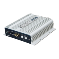
Identifies and describes the various power supply and output terminals on the amplifier.
Step-by-step guide for correctly mounting fast-on type connectors.
Explains the function and connection of services like SUB VOL and Remote IN/OUT.
Instructions for accessing the amplifier's control panel by removing and reassembling the cover.
Details Auto Turn-ON, Remote OUT, and SUB VOL connector usage.
Step-by-step instructions for replacing the amplifier's internal fuse.
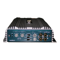
Visual representation of the LRx 6.9 amplifier's control panel and its components.
Explanation of the various output modes for amplifier channels.
Guide to setting the input sensitivity level from 0.3 to 5 Volts for optimal performance.
Specifies filter settings for configurations 1, 2, 3, 7, 9, and 10.
Specifies filter settings for configurations 4, 5, 6, 8, 11, and 12.
Specifies filter settings for configurations 1, 2, 4, 6, 13, and 14.
Explains the settings and usage of the subsonic filter.
Explains the meaning of various LED indicators for amplifier status.
Describes the amplifier's protection modes and associated LED signals.
Explains the meaning of various diagnostic LED indications for amplifier status.
Detailed instructions on how to physically install and secure the amplifier.
Explains how to use the provided template for planning amplifier mounting.
Steps for flush mounting the amplifier onto a panel.
Steps for semi-recessed installation of the amplifier.
Guidance on selecting appropriate speaker and power cables based on system requirements.
Formula and table to determine system current draw for proper cable sizing.
Diagram illustrating cable types and components, along with routing recommendations.
Details on filter settings and input configuration modes for various channel setups.
Diagram for a 6-channel, 3-way multi-amplified system setup.
Diagram for a 5/6 channel system with front, rear, and mono subwoofer.
Wiring diagram for a 3-channel setup with front speakers and a mono subwoofer.
Illustrates a 3-way multi-amplified setup with model combinations.
Wiring diagram for a 4-channel system featuring mid-high and woofer speakers.
Explains how to use pre-drilled cards to assist in setting amplifier controls.
Shows an example of applying cards to set controls for a 3-way active system.
Technical data for power supply, amplifier stage, distortion, bandwidth, S/N, and sensitivity.
Details output power ratings and specifications for inputs, outputs, and filters.
Amplifier performance data measured according to the CEA-2006 standard.
Details Audison's proprietary method for measuring amplifier power output.
Lists all items included in the product packaging for the LRx 6.9 amplifier.
Warning about high sound pressure levels and safe listening practices.
General instructions for installing ECI interface modules into the amplifier.
Guidance for installing the ECI module in a reversed configuration.
Steps for removing and reassembling the protective cover of the power supply panel.
Instructions for changing and using terminal plates for cable routing.
Identifies and describes the various power supply and output terminals on the amplifier.
Step-by-step guide for correctly mounting fast-on type connectors.
Explains the function and connection of services like SUB VOL, Speaker ON, and Remote IN/OUT.
Instructions for accessing the amplifier's control panel by removing and reassembling the cover.
Explains Auto Turn-ON with SPK ON and Remote OUT functionality.
Step-by-step instructions for replacing the amplifier's internal fuse.
Visual representation of the LRx 6.9 amplifier's control panel and its components.
Explanation of the various output modes for amplifier channels.
Guide to setting the input sensitivity level from 0.3 to 5 Volts for optimal performance.
Specifies filter settings for configurations 1, 2, 3, 7, 9, and 10.
Specifies filter settings for configurations 4, 5, 6, 8, 11, and 12.
Specifies filter settings for configurations 1, 2, 4, 6, 13, and 14.
Explains the settings and usage of the subsonic filter.
Explains the meaning of various LED indicators for amplifier status.
Describes the amplifier's protection modes and associated LED signals.
Explains the meaning of various diagnostic LED indications for amplifier status.
Detailed instructions on how to physically install and secure the amplifier.
Explains how to use the provided template for planning amplifier mounting.
Steps for flush mounting the amplifier onto a panel.
Steps for semi-recessed installation of the amplifier.
Guidance on selecting appropriate speaker and power cables based on system requirements.
Formula and table to determine system current draw for proper cable sizing.
Diagram illustrating cable types and components, along with routing recommendations.
Details on filter settings and input configuration modes for various channel setups.
Diagram for a 6-channel, 3-way multi-amplified system setup.
Diagram for a 5/6 channel system with front, rear, and mono subwoofer.
Wiring diagram for a 3-channel setup with front speakers and a mono subwoofer.
Illustrates a 3-way multi-amplified setup with model combinations.
Wiring diagram for a 4-channel system featuring mid-high and woofer speakers.
Explains how to use pre-drilled cards to assist in setting amplifier controls.
Shows an example of applying cards to set controls for a 3-way active system.
Technical data for power supply, amplifier stage, distortion, bandwidth, S/N, and sensitivity.
Details output power ratings and specifications for inputs, outputs, and filters.