Assembly Instruction
M-COM
INSTALLATION
INSTALLATION STEP 1: INSTALLATION
¢ Mount the drives according the instructions for in-
stallation the drives.
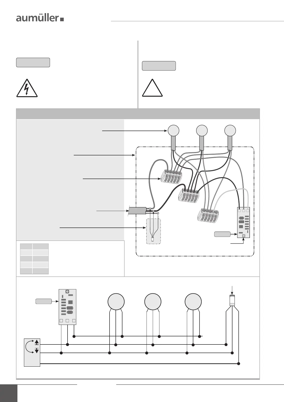
¢ Connect the multi-drive system to the M-COM and to
the supply line.
Before installation make sure, that there is no
voltage applied to the supply line!
Do not connect the WH-wire of the end
module to the WH-wire of the drives!
Connection: multi-drive system with M-COM
LED
line end module
M-COM
drives connected in a multi-drive system
max. 4 opening and 2 locking drives
plug connections site-supplied
size depends on the number of drives and
wire section
line end module
only with SHEV as a monitoring in the last box
24 V DC supply line / control unit
junction box site-supplied
M2M1 Mx
BN
BU
WH
BU
BN
WH
BU
BN
WH
BU
BN
WH
BN
BU
BK
BK
OG
+
+
-
-
M-COM
Control unit
BK = black
BN = brown
BU = blue
OG = orange
WH = white
2
NOTE
NOTE
24V-drives with version S12 / S3 (soft-
(ware version SW-V2) required.
In SHEV case t additionally the line end
module into the last junction box.