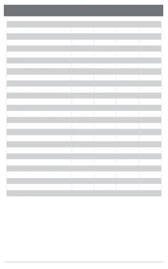
7.Technical Data
Recommended PV Module Power Range / W
(400~600)x 2
17x 2
20x 2 20x 2
17x 2
20x 4
25x 4 25x 4
20x 4
22-55
24
80
800
II II II II
230
Configurable
3.48
9.6A 9.6A
18A 18A
50 / 60 50 / 60 50 / 60 50 / 60
<3%
III
-40~65
0-100%
268 x 250 x 42 268 x 250 x 42
2.9
MC4 MC4MC4
Daisy Chain AC Bus
PLC or WiFi
97.1%
>99.5%
>0.99 >0.99 >0.99
10 years 10 years 10 years
>99.5% >99.5%
97.1% 97.1%
PLC or WiFi PLC or WiFi
Daisy Chain AC Bus Daisy Chain AC Bus
2.9 5.33
0-100% 0-100%
-40~65 -40~65
III III
<3%<3%
4.34
9.62
Configurable Configurable
230 230
1000 2000
80 80
6060 60
24 24
22-55 22-55
(500~750)2 (500~700)x 4
MPPT Voltage Range / V
Startup Voltage / V
Max. Input Voltage / V
Max. Input Current / A
Max. DC Short Circuit Current/A
Night Power Consumption / mW
Rated Output Power /W
DC Overvoltage Protection Category
Rated Output Voltage / V
Nominal Output Voltage Range / V
Max. Continous Output Current / A
Nominal Frequency / Range / Hz
Power Factor (Nominal/Adjustable Range)
Max. AC Fault Current
THDi@Rated Power
AC Overvoltage Protection Category
Operating Ambient Temperature Range / ℃
Relative Humidity Range
Dimensions (W x H x D) / mm
Weight / kg
DC Connector Type
AC Connection Type (inverter-inverter)
Communication Method
Protection Class
Peak Efficiency
MPPT Efficiency
Warranty
AU-1P8002G AU-1P10002G AU-1P16002G
MC4
>0.99
10 years
>99.5%
97.1%
PLC or WiFi
Daisy Chain AC Bus
5.33
300 x 233 x 38 300 x 233 x 38
0-100%
-40~65
III
<3%
6.52
Configurable
230
1600
80
60
24
22-55
(400~600)x4
AU-1P20002G
Austa Microinverter User Manual
14
IP-66 /67 IP-66 /67 IP-66 /67 IP-66 /67