Note:
The voltage of modules (considering the effect of local temperature) must not exceed the maximum
input voltage of the microinverter. Otherwise, the microinverter maybe damaged (refer to the
Technical Data section to determine the absolute maximum input voltage).
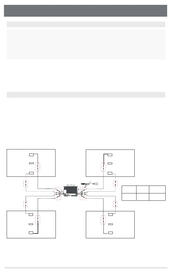
5.Microinverter Installation
Step 1. Plan and Install the Microinverter
Step 2. Connect PV Modules
Note:
1.Microinverter installation and DC connections must be done under the PV module to avoid direct
sunlight,rain exposure, snow buildup, UV etc.
2.Leave a minimum of 2 cm of space around the microinverter enclosure to ensure ventilation and
heat dissipation.
Note:
1. Make sure that the AC Connectors are kept away from any drainage channels.
2. In case you need to remove the microinverter AC cable from interface, Removal is accomplished by
inserting an MC4 spanner into the side connector.
3. The order of Step 1 and Step 2 can be reversed according to your planned needs.
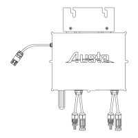
Before you install, you should have the following devices:
MicroInverter
Required photovoltaic modules
Mounting brackets according to your installation design
AC cable and solar cables that meet your requirements in length
Suitable installation tools and no less than 2 people
A) Mount the PV modules above the microinverter.
B) Connect the PV modules’ DC cables to the DC input side of the microinverter. Wait five minutes
and you'll see the LED will turn red and flashing.
A B
C
PV module DC cable
Microinverter
Austa Microinverter User Manual
9
1
2
3
+
-
+
-
+
-
+
-