GENERAL MARTI'ENANCEAUSTIN-HEALEY SPRITE
Rear Flasher Light.
1. Glass cover retaining
ring.
2. Flasher glass cover.
3. Bulb.
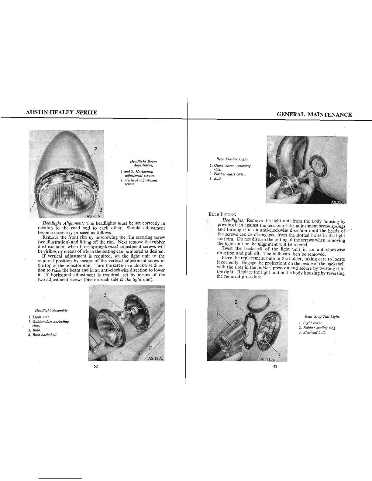
Headlight Beam
Adjustment.
1 and 3. Horizontal
adjustment screws.
2. Vertical adjustment
screw.
@kg<;4
s
BULB FITTING
pressing it in against the tension of the adjustment screw springs
and turning it in an anti-clockwise direction until the heads of~
the screws can be disengaged from the slotted holes in the light
unit rim. Do not disturb the setting of the screws when removing
the light unit or the alignment will be altered.
Twist the backshell of the light unit i n an anti-clockwise
direction and pull oK. The bulb can then be removed.
Place the replacement bulb in the holder, taking care to locate
it correctly. Engage the projections on the inside of the backshell
with the slots i
+he holder, press on and secure by twisting it to
the right. Replace the light unit in the body housing by reversing
the removal procedure.
Headlights: Remove the light unit from the body housing by
Headlight Alignment: The headlights must be set correctly in
relation to the road and to each other. Should adjustment
become necessary proceed as follows:
Remove the front rim by unscrewing the rim securing screw
(see illustration) and lifting oK the rim. Next remove the rubber
dust excluder, when three spring-loaded adjustment screws will
be visible, by means of which the setting can be altered as desired.
If vertical adjustment is required, set the light unit to the
required position by means of the vertical adjustment screw at
the top of the reflector unit. Turn the screw in a clockwise direc-
tion to raise the beam and in an anti-clockwise direction to lower
it. If horizontal adjustment is required, set by means of the
two adjustment screws (one on each side of the light unit).
Headlight Assembly
1. Light unit.
2. Rubber dust excluding
ring.
3. Bulb.
4. Bulb backshelh
Rear Stop/Tail Light.
1. Light cover.
2. Rubber sealing ring.
3. Stop/tail bulb.
53
52