AUSTIN-HEALEY SPRITE GENERAL MAINTENANCE
LH FLASHER dSIDE LAMP L . H .HEADLAMP
R.H HEADLAMP R.H.PLASHER dSIDELAMP
Rear Number Plate Light.
-1. Bulb.
2. Light glass.
3. Light cover.
18
57
9 9 HORN
DYNAMO
STOP LAMP
SWITCH
Do — 25
12 V. +~
I
SWITCH
I=
IGNITION COIL
Side and Flasher Lights: Move back the rubber lip, insert
a coin or screw-driver blade under the glass retaining collar and
gently lever the collar out from the light body. This will
enable the light glass to be completely removed, leaving the
bulb accessible in its socket.
Stop-Tail Lights: Remove the two cover securing screws and
lift off the cover to gain access to the bulb.
Rear Number Plate Light: Undo the one bolt and the cover
can be removed to give access to the bulb.
Panel Lights: The holders can be pulled from their fittings at
the back of the instrument panel and the bulbs are then easily
Ignition and Head1ight Beam Warning Lights: The bulbs can
be unscrewed from their holders when pulled out from the back
of the instrument panel.
Fuses: The fuse unit is situated adjacent to the voltage regu-
lator on )he right-hand side of the engine bulkhead and contains
two fuses and two spare.
IL~
't'-t
removed.
I
WIPER
MOTOR
o -
'
WIPI.R
SW IT C H
WD LAMP
57
(WVEH OTEDI
P
T I I v
FLASVER SWITCH
I
~j,r,(V:M ~ <..'..
I
REG. d
CUT-OUT
57
YF HEATER HOTOR
(WHEW FITTED)
DISTRIBUTOR
17-
-- — — — — — 4
!AI A2
IT
J
41
HORN
PUSH
U NIT
I
SPEEDOMETER
R.H. STOP d
TAIL LAMP
TACHOMETER
!WHEW FITTED
)
I — 41
COLOUR CODE
57
Regulator and Fuse Unit
1. Regulator cover.
2. AUX. IGN. fuse
(35 amps.)
3. Fuse unit.
4. AUX. fuse (35 amps.)
5. Spare fuses.
BLUE
2 BLUE
4 B LUE
WHITE 55
9 WHITE
16 WHIIE • BLACK
17 GREEN
IB GREEN IDEO
21 GAEEN » 'TIHITE
22 GREEN PURPLE
25 GREEN BROWN
24 GREEN BLACK
25
RED 29
SB
4O
41
44
57
62
66 LIGHT GREEN
YELLOW
YELLOW w TH GREEN
BROWN
B ROWN • BLU E
BROWN w TH GREEN
BROWN w<TH BLACK
RED
RED w T H WHITE
BLACK
B LACK' GREEN
TAH. LAMP
LH. FLASHER
LAMP
E.I495.
LAMP
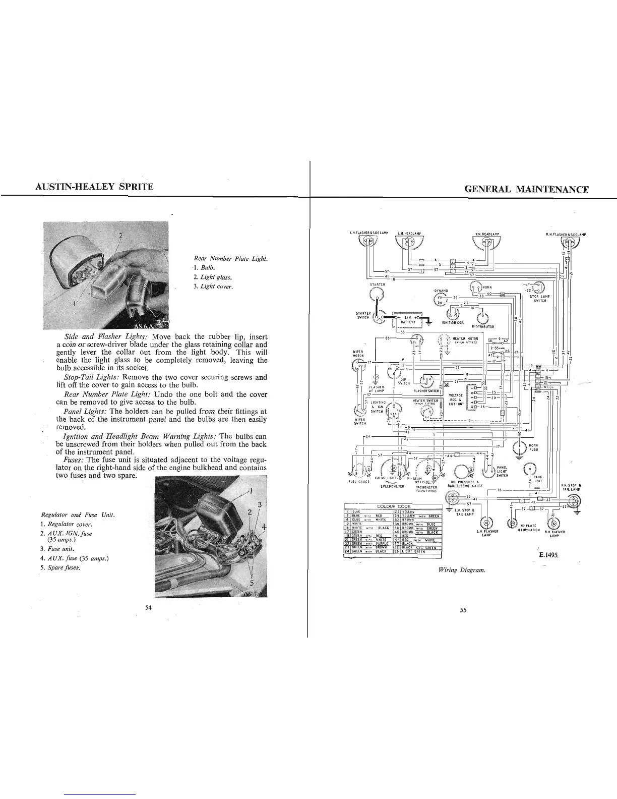
Wiring Diagram.
54