Do you have a question about the AUTEC LK NEO 6 and is the answer not in the manual?
Outlines the manual's structure and parts for clarity.
Defines key terms used throughout the manual for consistent understanding.
Explains the meaning of important symbols used in the manual for safety and information.
Identifies the intended audience and responsible parties for the manual's instructions.
Provides guidance on how to store the manual for future reference and compliance.
Details restrictions and rights related to the manual's content and proprietary information.
Introduces the Autec Air series radio remote controls and their basic unit components.
States the product's compliance with relevant industry standards and regulations.
Lists Autec's contact information and where to find distributors and service centers.
Provides general information on warranty conditions and where to find detailed terms.
Guides users on how to obtain technical support and order replacement parts.
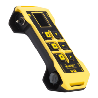
Details the physical components and layout of the LK NEO 6 and 8 transmitting units.
Details the physical components and layout of the LK NEO 6 DF transmitting unit.
Lists specifications such as power supply, dimensions, and run time for specific models.
Lists specifications such as power supply, dimensions, and run time for the LK NEO 6 DF model.
Explains the purpose and content of the Technical Data Sheet, including installer responsibilities.
Identifies and describes the plates found on the transmitting unit for standard remote controls.
Identifies and describes plates on transmitting units for "Take & Release" configurations.
Identifies and describes plates on transmitting units for "Multi Units" or "Multi Receiver" setups.
Explains the meaning of red and green LEDs indicating status on LK NEO 6/8 units.
Explains the meaning of LEDs, battery icon, and radio link icon on LK NEO 6 DF units.
Details the use, insertion, and removal of mechanical keys and Key ID 0-1 for powering the unit.
Explains the function of the START pushbutton for initiating operation and activating the horn.
Describes the function of the STOP pushbutton for immediate machine stoppage and unit shutdown.
Explains the function of the FUNCTION pushbutton, as defined by the installer.
Details the functions of the DISPLAY pushbutton, including lighting and scrolling information.
Describes the three-position enabling switch and its role in activating commands.
Covers battery insertion, removal, and charge level indication for the transmitting unit.
Explains the function of the ID internal tx memory key for coding messages.
Describes the Zero-G sensor, its activation causes, and potential unit behaviors upon activation.
Details the vibration alarm feature on LK NEO 6 DF units for specific signal notifications.
Outlines procedures for starting the remote control using power keyswitch or PIN code.
Details the procedure for starting the remote control using a PIN code without a keyswitch.
Details the procedure for starting the remote control using both a power keyswitch and PIN code.
Explains how to modify the PIN code for limiting remote control usage.
Explains how to activate machine movements and functions using the remote control.
Describes actions taken and LED signals during radio link interruptions.
Explains automatic switch-off conditions due to low battery or inactivity.
Describes how low battery levels are indicated by the unit's LEDs.
Explains the automatic switch-off mechanism when the unit is inactive.
Provides instructions for voluntarily switching off the transmitting unit.
Explains how the "Data Feedback" function uses LEDs or displays to convey machine status.
Details the use and setup of a backup transmitting unit for replacement.
Lists restrictions for users, especially regarding electronic devices and safe operation.
Outlines user responsibilities, compliance, and safe operating practices.
Explains how to assemble and use the belt and pouch for carrying the unit.
Provides step-by-step instructions for assembling the belt or harness.
Provides step-by-step instructions for assembling the pouch with belt.
Lists LED signals, their possible reasons, and initial troubleshooting steps.
Continues detailing LED signals, their causes, and recommended solutions for malfunctions.
| Protection Degree | IP65 |
|---|---|
| Frequency | 433 MHz |
| Channels | 6 |
| Model | LK NEO 6 |
| Category | Transmitter |
| Brand | AUTEC |
| Frequency Range | 433.05 - 434.79 MHz |