Do you have a question about the Autel MaxiIM IM608 II and is the answer not in the manual?
Explains hazard levels using signal words like DANGER and WARNING.
Covers situations Autel is aware of and user responsibility for safety.
Explains formatting conventions like Bold Text, Notes, and Hyperlinks used in the manual.
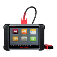
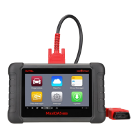
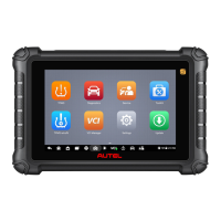
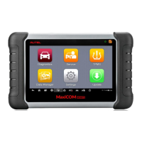
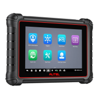
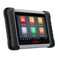
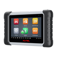
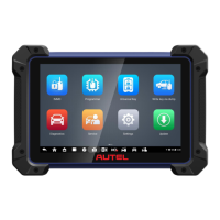
Describes the central processor and monitor for the MaxiIM system.
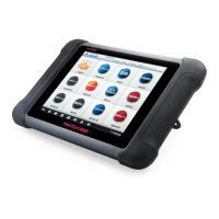
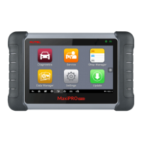
Describes the device for accessing vehicle data.
Describes the programmer for performing programming functions.
Explains how the tablet can receive power from internal battery or external supply.
Details the functions and ports of the MaxiFlash JVCI+ interface device.
Explains the MaxiFlash JVCI+'s capability for ECU software replacement and programming.
Describes the MaxiFlash JVCI+'s support for Bluetooth and USB communication.
Describes the Main Cable V2.0 for connecting the MaxiFlash JVCI+ to the vehicle's DLC.
Lists other accessories included with the kit, such as USB cables and adapter.
Explains how to power on the tablet using the Power/Lock button.
Describes shortcuts for Wi-Fi, Bluetooth, Battery status, Flashlight, and other settings.
Explains the procedure to properly shut down the tablet, emphasizing terminating vehicle communication first.
Details steps to connect the MaxiIM tablet to the vehicle via MaxiFlash JVCI+.
Explains connection methods based on vehicle's OBDII system configuration.
Describes connecting to vehicles with an OBDII system using the main cable.
Explains connecting to non-OBDII vehicles, including conditions and adapter usage.
Recommends and details the process for pairing the tablet with the VCI via Bluetooth.
Explains establishing communication between the tablet and VCI using a USB cable.
Provides troubleshooting steps for communication errors between the tablet and VCI.
Explains the VIN-based Auto Detect function for identifying vehicles.
Details how to manually enter vehicle VIN for identification when Auto Detect is not supported.
Explains using the scanner to identify vehicle information via VIN or license plate.
Details buttons in the operation toolbar like Print, Save, and Data Logging.
Explains informational messages that cannot be reversed.
Explains warning messages about potential irreversible changes or data loss.
Explains error messages indicating system or procedural faults.
Describes comprehensive scanning of IMMO ECU for fault systems and DTCs.
Details how scanned systems and results are displayed with status indicators.
Displays detailed information about the tested control unit, including versions and specifications.
Describes the screen for selecting EEPROM, MCU, or ECU for chip read/write operations.
Details the menu for selecting 'Read' operation for chip data.
Explains how to save chip data to the tablet with a file name.
Details the process of writing saved data to a blank chip.
Performs a comprehensive scan of all ECUs to locate faults and retrieve DTCs.
Describes buttons for Report, Quick Erase, Fault Scan, Pause, Enter System, and ESC.
Clears emission-related diagnostic data, DTCs, and freeze frame data from the ECM.
Checks the readiness of the monitoring system for state emissions programs.
Displays real-time PID data from the ECU in various modes.
Describes buttons for Cancel All, Show Selected/Show All, and Graph Merge.
Performs component adaptations, recalibrations, or configurations after repairs.
Explains how to access OBDII/EOBD diagnostics functions.
Captures critical parameter values at the time a DTC is set.
Clears emission-related diagnostic data, DTCs, and freeze frame data.
Allows viewing of On-Board Monitor test results after servicing.
Enables bi-directional control of the ECM to test vehicle systems and components.
Allows resetting the Engine Oil Life system after an oil change.
Manages the electronic braking system, including deactivating/activating and brake pad settings.
Provides safety rules to follow before performing EPB system maintenance.
Evaluates battery charge state, monitors current, and registers battery replacement.
Describes buttons for changing display sequence and performing bulk updates.
Allows adjustment of the display language for the MaxiIM system.
Allows printing data via Wi-Fi connection.
Allows sorting vehicles by alphabetical order or frequency of use.
Provides access to Android system settings like wireless, sound, and security.
Provides information about the MaxiIM diagnostic device, including product name and version.
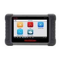
Provides detailed data of tested vehicles, including service records and DTCs.
Allows creating and editing customer accounts correlated with vehicle history records.
Stores and displays diagnostic reports, with options to view or share them.
Stores and displays all PDF files of saved data.
Allows playback of recorded data frames from live data streams.
Allows launching the Support platform to view data loggings.
Manages firmware applications, allowing uninstallation of selected ones.
Displays comprehensive user and product information synchronized with the online account.
Details user information and device information within the Personal Info tab.
Lists the product's software update history, including version and time.
Displays a record list of the device's service history information.
Provides quick links to Autel's online video accounts for technical support and tutorials.
Records and manages data loggings, allowing interaction with support personnel.
Provides references for frequently asked questions about the online account, shopping, and payment.
Details how to update VCI software via the internet using the MaxiIM tablet.
Details safe operating ranges and precautions for preventing electric shock.
Explains grounding requirements and precautions for safe operation.
Safety warning regarding the use of power cords and adapters.
Safety warning about operating in wet/damp conditions or near explosive gases.
Information on product maintenance, repair, and handling precautions.
Controls the time interval displayed across the oscilloscope screen.
Defines the range of voltages that can be accurately captured by the oscilloscope.
Describes waveform characteristics typically found in circuits with large inductance and capacitance.
Describes waveform characteristics of signals switching between defined voltage levels.
Indicates the voltage difference between minimum and maximum waveform points.
Describes the USB port for connecting the MaxiScope module.
Details the input channels for connecting probes.
Explains the status indications of the LED indicator light.
Symbol indicating potential safety hazards and the need for precautions.
Symbol indicating BNC connectors are at the same potential, requiring precautions.
Saves and prints a copy of the displayed data.
Opens settings for measurement tools like Math Channel, Probe, and Cache.
Opens submenu for saving, recording, and playing back waveform data.
Provides instructions or tips for operations of various functions.
Saves existing signal waveforms as references for comparative analysis.
Includes buttons for trigger settings (source, slope, mode) and time base.
Shows how to maintain devices with precautions for cleaning and handling.
Lists common issues when the tablet does not work properly.
States compliance with FCC rules and Industry Canada's license-exempt RSSs.
Information on Specific Absorption Rate (SAR) and radio frequency exposure limits.
Statement regarding the device's evaluation for general RF exposure requirements.
Declaration of compliance with the European RoHS Directive.
Declaration of conformity with essential requirements of EU Directives.
| Display Size | 10.1 inches |
|---|---|
| Resolution | 1920 x 1200 pixels |
| RAM | 4 GB |
| Storage | 128 GB |
| Battery Capacity | 15000 mAh |
| Rear Camera | 16 MP |
| Connectivity | Wi-Fi, Bluetooth |
| Processor | Samsung Exynos 8895 |
| Operating System | Android |
| Ports | USB Type-C |
| Protocols | DoIP |